English
 Español
 Português
 Français
 Deutsch
 русский
 한국어
 にほんご
 हिन्दी, हिंदी
 বাংলা
 Bahasa Indonesia
 Türkçe
 Việt
 dansk
 čeština
 עִבְרִית Ivrit
 Filipino/Pilipino
 български език (Bǎlgarski jazik)
 suomi
 norsk
 język polski
 ไทย
 ກະຣຸນາ
 Bahasa Melayu
 ភាសាខ្មែរ
 ဗာရမ်
 اردو
 فارسی
 Italiano
 Nederlands
 svenska
 Монгол хэл
 नेपाली
 සිංහල
 Ўзбек тили
 پښتوتۆرکجه
 Ελληνικά
 српски / srpski
 magyar
 українська
 Kiswahili
 Қазақ тілі
 Română
 Hrvatski
 Bosanski
 Kreyòl ayisyen
 አማርኛ
 Hausa
 Yorùbá
 Igbo
Building Industrial Maintenance Safety Solutions for High-Risk Electrical Work
Safety Has to Be Designed Into the Maintenance Job
High-risk electrical maintenance is often treated as a procedural problem: issue a permit, isolate the equipment, brief the crew, and begin work. Those controls matter, but they do not by themselves create a reliable safety system. A maintenance team can have a sound work instruction and still face serious exposure if the isolation point is unclear, temporary grounding is poorly selected, insulated tools are damaged, or protective equipment has not been verified for its intended duty.
For safety managers and quality control teams, industrial maintenance safety solutions should be built around the actual electrical work being performed, not around a generic inventory of protective products. The objective is to prevent an unexpected energization, control induced or backfeed voltage, limit worker exposure to live parts, and ensure that the tools brought to site will perform as expected under field conditions.
The strongest approach combines job-specific risk assessment, controlled work methods, compatible protective equipment, traceable inspection, and clear responsibility at every handover. It also recognizes an uncomfortable reality: safety equipment that is correct on paper can be ineffective when it is unavailable, mismatched, contaminated, expired, improperly stored, or used outside its operating limits.
Start With the Energy Path, Not the Product List
Before selecting equipment, the maintenance team needs a practical picture of how energy can reach the work location. In a substation, industrial plant, renewable energy installation, or utility network, the obvious incoming supply is only one part of the picture. Energy may also be present through parallel circuits, generator connections, stored energy, capacitive charge, induced voltage, battery systems, automatic transfer equipment, or remote control functions.
A useful maintenance safety plan asks several direct questions:
- What conductors, terminals, busbars, or components will be approached or touched?
- Which normal and abnormal sources could energize them?
- Can isolation devices be locked, identified, and verified at the point of work?
- Could another circuit introduce voltage after the primary source is isolated?
- Is temporary protective grounding required after absence of voltage has been established?
- What fault level, voltage class, environmental exposure, and access constraints apply?
This exercise changes the quality of the solution. For example, a lockout device may control a local disconnect, but it does not address induced voltage on a disconnected overhead conductor. A voltage detector may support verification, but it cannot compensate for an inaccessible isolation point or an unclear switching boundary. Electrical safety tools are effective when they are placed within a defined energy-control sequence.
For planned maintenance, the sequence should be prepared before the crew arrives at the equipment. For fault response or urgent repair, the same logic still applies, although the work package must be concise enough for the field team to use under time pressure. A long generic procedure that cannot be followed during an outage is less valuable than a short, site-specific control plan with unambiguous isolation, test, grounding, and restoration steps.
Control the Work in the Correct Order
Many incidents develop from a breakdown in work sequence rather than from a single missing item. A dependable electrical maintenance process establishes the condition of the equipment before personnel enter the exposure zone.
1. Identify and isolate every credible source
Isolation begins with accurate equipment identification. Labels, single-line diagrams, switching records, physical tagging, and field verification should point to the same asset. Where labels are incomplete or the layout has changed, the job should pause until the boundary is resolved. Guessing at an isolation point is not a manageable maintenance risk.
The isolation method must also match the source. Mechanical locking may be appropriate for a breaker, switch, valve, or local disconnect. Remote control systems may require additional controls to prevent automatic or supervisory operation. Where stored energy is present, it must be discharged or restrained using a method suitable for the equipment design.
2. Secure the isolation against interference
Lockout and tagout controls need to make the work status visible and difficult to defeat accidentally. In multi-person maintenance, group lockout arrangements should show who remains exposed and who has authority to remove the lock. Safety management should avoid informal arrangements in which one person holds the only key or a tag is used as a substitute for a lock where physical locking is possible.
Quality teams can add substantial value here by checking whether lockout hardware fits the site’s actual devices. A well-made lock is of limited use if it cannot secure the installed disconnect handle, cabinet door, plug, valve, or control station. Compatibility checks should be part of site standardization, especially after equipment upgrades or when maintenance is performed across multiple facilities.
3. Verify absence of voltage at the work point
Verification is a separate control, not a formality after isolation. The test point should be as close as practical to the location where work will occur, using equipment suitable for the system and task. The testing method should account for accessible live parts, enclosure design, phase arrangement, environmental conditions, and the possibility of erroneous readings.
Teams should establish a controlled method for confirming that the voltage detector itself is functioning before and after the test, where the device design and work procedure call for it. This avoids relying on a failed or unsuitable instrument to declare equipment safe. The worker performing the verification also needs clear authority to stop the job when the result does not match the planned condition.
4. Apply temporary protective grounding where the hazard requires it
Temporary grounding is one of the most misunderstood elements of electrical maintenance safety. It is sometimes treated as a universal accessory and sometimes omitted because the circuit has already been opened. Neither approach is adequate. The need for temporary grounds depends on the system configuration and the credible hazards at the worksite, including accidental energization, induced voltage, static charge, and backfeed.
When grounds are required, their selection and installation must be engineered for the application. Grounding sets should have the appropriate conductor capacity, clamp design, connection points, cable length, and phase configuration. The connection sequence, location, and removal process must be clear. A grounding set that cannot reach the approved points without excessive tension, sharp bends, or improvised extensions introduces a new source of failure.
Grounding equipment should also be treated as controlled protective equipment, not as ordinary cable. Damaged clamps, compromised cable strands, corroded contact surfaces, missing protective covers, and unclear identification can undermine its intended performance. Routine visual inspection is necessary, but it should sit within a documented inspection and replacement program.
Match Protective Equipment to the Exposure
Industrial maintenance safety solutions often fail at the selection stage because equipment is grouped under broad labels such as “insulated,” “arc protective,” or “high voltage.” Those labels do not answer whether an item is suitable for a particular task. Selection should begin with the exposure, then move to the equipment characteristics required to control it.
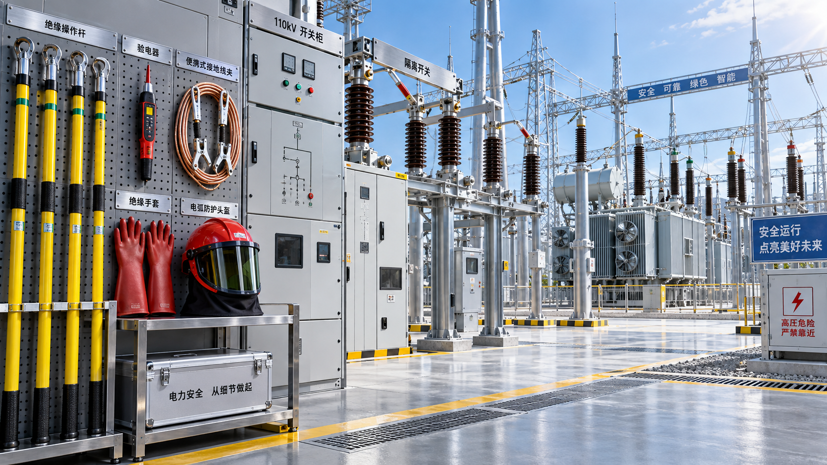
Insulating gloves, sleeves, blankets, covers, hot sticks, rescue equipment, voltage detectors, grounding sets, lockout devices, and arc-protective clothing each serve distinct purposes. They should not be treated as interchangeable layers of protection. For example, insulated hand tools may reduce the consequence of incidental contact during an appropriate task, but they do not authorize work on energized equipment. Likewise, arc-protective clothing addresses thermal exposure under defined conditions; it does not remove the need to control the electrical source.
Safety managers should also look beyond initial conformity documents. The relevant questions include whether equipment has a clear identification system, whether its inspection status can be determined in the field, whether replacement parts remain available, and whether workers can use it correctly while wearing other required protective equipment. A technically compliant item that is awkward, too heavy, poorly sized, or difficult to deploy may be bypassed when work pressure increases.
Build Quality Control Around Condition and Traceability
For electrical protective tools, quality assurance continues after manufacturing acceptance. The equipment can be damaged during transport, storage, cleaning, issue, and use. An effective control system therefore tracks both the original product specification and the equipment’s current condition.
A practical inspection program separates three levels of control. The first is the user check before each use: cleanliness, cracks, cuts, burns, loose fittings, degraded insulation, missing labels, unusual stiffness, contamination, and visible mechanical damage. The second is scheduled inspection by a designated competent person, including functional checks and review of service history. The third is periodic testing or recertification where the equipment type, governing standard, manufacturer instruction, or site procedure requires it.
The process should make it easy to quarantine suspect equipment. Workers need a simple way to remove an item from service without debating whether it is “probably fine.” A clear hold tag, segregated storage location, inspection record, and disposition decision prevent damaged tools from returning to circulation by mistake.
Traceability matters most when it supports action. Recording every serial number without linking it to inspection status, location, test history, or replacement decisions creates administrative effort without improving protection. Conversely, a basic digital or controlled paper register can be highly effective when it allows the safety team to answer practical questions quickly: Is this grounding set approved for this location? Has this voltage detector been inspected? Which insulated tools are due for review? Has a recalled or damaged batch been removed from issue?
Storage and Logistics Are Part of Electrical Safety
Electrical protective equipment is frequently procured with care and then undermined by poor storage. Rubber insulating goods may be exposed to heat, sunlight, ozone-producing equipment, sharp objects, oils, chemicals, or crushing loads. Hot sticks and other insulated tools can be compromised by rough handling, surface contamination, moisture, or unsuitable vehicle storage. Grounding sets can suffer cable damage and corroded connections when thrown into mixed tool containers.
The safety solution should define where equipment is stored, how it is transported, who checks it when it is issued, and how it is cleaned and returned. Separate protective equipment from general mechanical tools and consumables. Provide protective cases or racks where the equipment design calls for them. Keep inspection labels visible rather than covering them with tape, paint, or site markings.
For distributed maintenance teams, standardized kits can reduce omissions, but only if the kits reflect the task. A substation switching kit, a cable maintenance kit, and a photovoltaic field service kit may share some items while needing different verification, grounding, access, and environmental controls. Standardization should reduce uncertainty, not force every crew into the same incomplete configuration.
Use Procurement Reviews to Test the Whole Safety System
Procurement decisions should assess more than unit price and a list of claimed standards. The purchase review is an opportunity to test whether the equipment will fit the work method, site assets, inspection capability, and replenishment process.
- Define the intended electrical and environmental duty before requesting quotations.
- Confirm dimensional compatibility with installed switchgear, grounding points, locking points, and storage arrangements.
- Review identification, instructions, inspection requirements, and available technical documentation.
- Check whether the supplier can provide consistent configuration for repeat orders rather than substituting critical components without control.
- Specify acceptance checks for incoming equipment, including labeling, completeness, visible condition, and documentation.
- Plan for replacement, testing, repair, and end-of-service disposal before issuing equipment to crews.
For organizations operating across regions, local electrical rules, client requirements, and site-specific procedures may differ. The safest purchasing approach is to set a common internal baseline, then identify the points that require local adaptation. This reduces the risk of sending a familiar but unsuitable kit to a new facility or contractor project.
A Safer Program Is One That Holds Up Under Work Pressure
High-risk electrical maintenance cannot depend on perfect memory or ideal conditions. The equipment, process, and quality controls should help workers make the safe choice when access is difficult, weather changes, production pressure rises, or a job extends beyond its original scope.
That is the practical standard for industrial maintenance safety solutions: can the organization establish a verified de-energized condition, control remaining energy, equip the crew for the specific exposure, and prove that its protective tools are fit for service? When those elements are connected, safety management becomes more than compliance paperwork. It becomes a repeatable operating discipline that protects people while allowing critical maintenance to proceed with confidence.
Recommend
 Oct 25, 2026
Homemade Bird Repellent Spray: Recipe Limits and Outdoor Surface Risks
Searching for how to make homemade bird repellent spray? Discover recipe limits, outdoor surface risks, electrical safety tips, and safer deterrents before you spray.
- Oct 25, 2026
Natural Bird Deterrents for Rooftops: Choosing Nonchemical Options
Learn how to repel birds naturally with humane rooftop barriers and smarter maintenance. Compare nonchemical options to protect electrical equipment and keep roof access clear.
- Oct 24, 2026
Home Remedies for Repelling Birds: What to Try on Patios and Railings
Learn how to repel birds with home remedies for cleaner patios and railings. Discover humane DIY options, avoid harmful sprays, and keep deterrents clear of electrical equipment.