 English
 Español
 Português
 Français
 Deutsch
 русский
 한국어
한국어 にほんご
にほんご हिन्दी, हिंदी
 বাংলা
বাংলা Bahasa Indonesia
 Türkçe
 Việt
Việt dansk
dansk čeština
 עִבְרִית Ivrit
 Filipino/Pilipino
 български език (Bǎlgarski jazik)
 suomi
suomi norsk
norsk język polski
 ไทย
ไทย ກະຣຸນາ
 Bahasa Melayu
 ភាសាខ្មែរ
 ဗာရမ်
ဗာရမ် اردو
اردو فارسی
فارسی Italiano
 Nederlands
 svenska
 Монгол хэл
 नेपाली
 සිංහල
සිංහල Ўзбек тили
 پښتوتۆرکجه
 Ελληνικά
 српски / srpski
 magyar
 українська
 Kiswahili
 Қазақ тілі
 Română
 Hrvatski
 Bosanski
 Kreyòl ayisyen
 አማርኛ
አማርኛ Hausa
Hausa Yorùbá
 Igbo
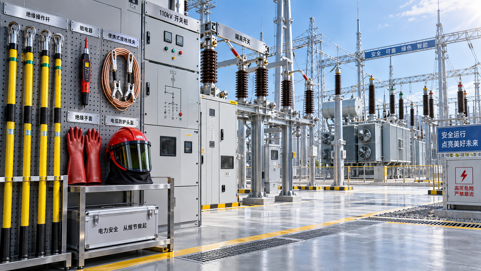
IgboDo Portable Grounding Systems Need a Cable for Each Phase?
A crew has isolated a three-phase circuit, verified the absence of voltage, and is ready to install portable protective grounds. The grounding set may appear straightforward: a ground-end clamp, several phase clamps, and flexible cables. Yet one decision can change the level of protection available to the work area: does each phase need its own grounding cable?
In most three-phase applications, yes. Each phase conductor should normally have a dedicated, properly rated grounding lead connected through an approved grounding assembly to the grounding point or ground cluster. A single cable serving multiple phases is not automatically acceptable merely because the conductors are close together or because the circuit has been de-energized. The configuration must provide a low-impedance fault-current path, control induced voltage, and create an equipotential work zone in accordance with the applicable work procedure and the equipment manufacturer’s ratings.
Why one cable is usually not enough for a three-phase system
Portable grounding is installed after isolation and absence-of-voltage testing because isolation alone does not remove every electrical hazard. A conductor can become energized by an operating error, backfeed from another source, induced voltage from nearby energized lines, stored energy, or incorrect switching conditions. If that happens, the portable grounding set must carry fault current long enough for protective devices to operate.
Each phase is electrically independent. Even when three conductors are part of the same circuit, any one phase may be the first to become energized or may carry the highest available fault current under a particular fault condition. A dedicated cable on each phase provides an intentional, known path from that conductor into the grounding arrangement.
Using only one cable on one phase does not reliably ground the other two phases. It may leave them floating, allow induced voltage to remain present, or create hazardous voltage differences between the conductor being handled and nearby conductive objects. Joining phases together with improvised jumpers does not solve the problem unless the assembly has been specifically designed, rated, and approved for that purpose.
Separate phase leads versus a complete grounding set
The phrase “separate cable for each phase” can be misunderstood. It does not necessarily mean that every phase needs an entirely separate route all the way to an independent earth connection. In many portable grounding sets, three individual phase leads connect to a common grounding cluster, grounding bar, or bonded ground-end connection. The important point is that each phase has its own suitably sized conductive path into the common grounded system.
A portable grounding assembly is a system, not just a collection of clamps and cables. Its safe performance depends on cable size, strand construction, clamp type, ferrule connections, grounding point condition, conductor material, fault-current rating, and the way the components are arranged. Replacing a specified three-lead set with a single lead changes that system.
The question to ask before installing grounds
Rather than asking only, “Do I need separate grounding cables for portable grounding equipment on each phase?”, begin with a more practical question: What grounding configuration is required to protect workers at this exact work location if the circuit becomes energized?
The answer depends on the work arrangement. A line crew working between two isolation points may require grounds positioned to protect against energization from either direction. Substation maintenance may involve multiple possible sources, bus sections, transformer backfeed paths, capacitor banks, or connected equipment. Industrial maintenance teams may encounter generator connections, photovoltaic systems, battery energy storage equipment, motor circuits, and control transformers that can introduce unexpected voltage.
For each possible source, determine whether the worksite grounding procedure requires a protective ground on every phase, a phase-to-phase bond in addition to phase-to-ground connections, grounding at one location or multiple locations, or a dedicated equipotential zone around the worker. The approved procedure for the installation takes priority over assumptions based on a previous job or a visually similar circuit.
When phase-to-phase bonding is also needed
Grounding each phase to earth is essential in many applications, but it may not be the only requirement. A worker can still be exposed if different conductive objects in the immediate work zone develop different potentials during a fault. This is why portable protective grounding often includes bonding between phases, between equipment frames and conductors, or between the conductor and the worker’s work position.
Consider a technician working on separated phase conductors. If one phase becomes energized and fault current flows through its grounding lead, voltage drop can occur along the lead and at connection points. The worker’s exposure depends not only on whether the phase is grounded, but also on whether the worker can bridge two points with different electrical potential. Proper equipotential grounding seeks to keep the items a worker may touch at substantially the same potential during the fault event.
Phase bonding may therefore be required by the work method, especially where workers can contact more than one phase or where induced voltage is significant. However, a phase bond should never be treated as a substitute for correctly installed grounding leads unless the grounding design explicitly permits that arrangement.
How to determine whether a grounding set is adequate
The cable count is only one part of the decision. Before a grounding set is selected or installed, the responsible person should verify the following conditions.
- Available fault current: The assembly must be rated to withstand the maximum fault current that could reach the grounding location for the required clearing time. Cable size alone does not establish adequacy.
- System voltage and configuration: Grounded-wye, ungrounded, impedance-grounded, delta, and mixed-source systems can behave differently during a fault.
- Potential sources of energization: Identify normal feeds, alternate feeds, tie connections, generators, transformers, renewable-energy backfeed, and induced voltage from adjacent circuits.
- Grounding point quality: A corroded structure, painted surface, unsuitable ground stud, or loosely attached clamp can limit performance even when the cable is correctly sized.
- Length and routing of leads: Longer leads generally add impedance. Leads should be arranged to avoid unnecessary loops, mechanical damage, pinch points, and exposure to fault arc conditions where possible.
- Condition of the assembly: Inspect cables for broken strands, heat damage, cuts, stiff sections, flattened areas, damaged ferrules, worn clamp jaws, weak springs, contamination, and missing identification.
A ground set marked for a particular duty should not be assumed suitable after components have been mixed from different sets. A phase clamp from one assembly, a cable from another, and a ground-end clamp from a third may not provide the intended rating as a complete system. The same concern applies to modified leads, field repairs, or cable extensions unless they are controlled under the organization’s approved process.
Installation order matters as much as cable quantity
A three-phase grounding set can be correctly selected but still create exposure if installed or removed in the wrong sequence. The usual protective principle is to establish the ground-end connection first, then apply the phase-end clamps using approved live-line tools or the required installation method. This gives each phase a path to ground as it is connected.
Removal is generally performed in reverse order: remove phase-end clamps first, then remove the ground-end connection last. This prevents a worker from handling a phase lead that has been disconnected from the grounding point while it remains attached to a conductor.
Exact steps vary by equipment type and local work rules, but the underlying logic remains the same. Do not attach phase clamps first and then search for a ground point. Do not remove the ground connection while phase clamps remain on conductors. And do not rely on visual isolation instead of completing the required absence-of-voltage test before grounds are installed.
Connection quality can defeat a good cable arrangement
A dedicated lead on each phase offers little protection if a clamp is attached to oxidized metal, insulation, a poorly conductive surface, or a point not intended to carry fault current. Clamps should be placed on clean, conductive, mechanically secure connection points designed for temporary grounding where available. The conductor should be gripped firmly, and the clamp should not be positioned where normal movement of the work could loosen it.
Ground-end locations deserve the same scrutiny. Equipment grounding conductors, station ground grids, structures, ground studs, and other points may have different capabilities. The correct connection point is determined by the approved grounding design, not simply by whichever metal component is nearest.
Situations where a single common lead may be permitted
There are applications in which a grounding assembly uses a common lead after the phases are connected through a purpose-built cluster or bonding device. This can be an acceptable arrangement only when the assembly is designed and rated for the expected fault duty and the work procedure calls for it. The common conductor, phase connectors, bonding bar, and ground connection must all be capable of carrying the required current without becoming the weak link.
This is different from placing one clamp on one phase and assuming the other phases are protected. It is also different from making a temporary phase-to-phase connection with cable that was never intended for protective grounding. The distinction is important: a rated assembly has known electrical and mechanical characteristics; an improvised arrangement does not.
Where the grounding configuration is not clearly defined, do not reduce the number of phase leads simply to make installation faster or to avoid handling a larger set. Confirm the required arrangement from the switching plan, grounding schedule, equipment documentation, and the responsible electrical authority before work begins.
Common field mistakes that create hidden exposure
One frequent error is treating a three-phase circuit as though it were one conductor because all phases are contained in the same cubicle, cable tray, or line structure. Another is assuming that an open disconnect guarantees every downstream conductor is safe. Open points can be misidentified, mechanically defective, bypassed by another source, or located where induction remains significant.
Crews may also overlook the difference between equipment grounding and protective grounding. An equipment frame bonded to ground does not automatically mean the phase conductors at the work location are protected by portable grounds. Protective grounding must address the conductor being worked on and the fault path that would exist if it were energized.
Finally, avoid using grounding leads as general-purpose jumpers, lifting aids, pulling lines, or temporary mechanical restraints. Damage to strands, ferrules, or clamps may not always be obvious during a quick visual inspection, yet it can reduce the assembly’s ability to carry fault current.
Questions that often come up at the worksite
Can one grounding cable be moved from phase to phase as work progresses?
Not while the other phases remain exposed and accessible as part of the work area. Moving a single lead may leave conductors ungrounded during the transition. Any change in grounding position should follow the approved work sequence and maintain required protection throughout the task.
Do insulated cables eliminate the need for separate phase grounds?
No. Insulation can reduce certain contact risks, but it does not remove the hazards of accidental energization, induced voltage, or fault current. The grounding method must be based on the electrical system and work procedure, not on the presence of conductor insulation alone.
Are portable grounds required on both sides of the work area?
They may be. Grounds on both sides can be necessary when the work location could be energized from more than one direction or when the work method requires a defined equipotential zone. The isolation plan and source analysis determine the required locations.
What should be done when the available grounding point is questionable?
Stop before installing the set and verify the approved grounding location. Do not attach portable grounds to a convenient metal surface without confirming that it is part of an adequate grounding path and is suitable for the expected fault duty.
Recommend
 Oct 25, 2026
Homemade Bird Repellent Spray: Recipe Limits and Outdoor Surface Risks
Searching for how to make homemade bird repellent spray? Discover recipe limits, outdoor surface risks, electrical safety tips, and safer deterrents before you spray.
- Oct 25, 2026
Natural Bird Deterrents for Rooftops: Choosing Nonchemical Options
Learn how to repel birds naturally with humane rooftop barriers and smarter maintenance. Compare nonchemical options to protect electrical equipment and keep roof access clear.
- Oct 24, 2026
Home Remedies for Repelling Birds: What to Try on Patios and Railings
Learn how to repel birds with home remedies for cleaner patios and railings. Discover humane DIY options, avoid harmful sprays, and keep deterrents clear of electrical equipment.