 English
 Español
 Português
 Français
 Deutsch
 русский
 한국어
한국어 にほんご
にほんご हिन्दी, हिंदी
 বাংলা
বাংলা Bahasa Indonesia
 Türkçe
 Việt
Việt dansk
dansk čeština
 עִבְרִית Ivrit
 Filipino/Pilipino
 български език (Bǎlgarski jazik)
 suomi
suomi norsk
norsk język polski
 ไทย
ไทย ກະຣຸນາ
 Bahasa Melayu
 ភាសាខ្មែរ
 ဗာရမ်
ဗာရမ် اردو
اردو فارسی
فارسی Italiano
 Nederlands
 svenska
 Монгол хэл
 नेपाली
 සිංහල
සිංහල Ўзбек тили
 پښتوتۆرکجه
 Ελληνικά
 српски / srpski
 magyar
 українська
 Kiswahili
 Қазақ тілі
 Română
 Hrvatski
 Bosanski
 Kreyòl ayisyen
 አማርኛ
አማርኛ Hausa
Hausa Yorùbá
 Igbo
IgboElectrical Maintenance Safety Equipment: A Practical Checklist for Field Teams
Electrical maintenance rarely begins in ideal conditions. A technician may be called to a feeder cabinet after an unexpected trip, inspect a substation bay during a shutdown, or replace damaged components where adjacent circuits remain energized. In each situation, the immediate risk is not limited to the part being repaired. Stored energy, backfeed, induced voltage, arc-flash exposure, damaged insulation, poor footing, and an incomplete isolation can turn a routine task into a serious incident.
The practical answer is to treat electrical maintenance safety equipment as a task-specific system rather than a collection of items carried to site. Before work starts, the team needs to confirm the energy condition, select protection for the credible hazards, inspect every protective device, and establish controls that remain effective until the work is complete. The checklist below focuses on what to prepare, what to verify, and what should stop the job.
Start with the work condition, not the equipment bag
It is tempting to begin by reaching for gloves, a voltage detector, and basic hand tools. That approach can miss the conditions that determine whether those items are adequate. A better starting point is a short review of the equipment being worked on and the possible paths by which it could become energized.
- Identify every normal supply, alternate supply, control supply, generator connection, battery source, and possible backfeed path.
- Determine whether nearby live conductors can create induced voltage on the isolated section.
- Check whether capacitors, cable circuits, transformers, or rotating machinery may retain stored energy.
- Consider the work position: elevated platforms, confined panels, wet ground, restricted access, or conductive structures all affect protection choices.
- Confirm whether the task involves testing, isolation, replacement, adjustment, or mechanical work close to energized parts. These are not equivalent risk conditions.
A lockout point that appears obvious on a simple drawing may not isolate a field installation fully. For example, a distribution circuit may still receive voltage through an interconnected section, a standby source, or an incorrectly identified cable. The purpose of the initial review is to make sure the isolation plan matches the actual installation, not merely the expected arrangement.
The first barrier: isolation, verification, and visible control
Personal protective equipment reduces exposure, but it does not replace de-energization. Where maintenance can be performed with the equipment safely isolated, isolation is the primary control. The sequence should be deliberate: disconnect the relevant supplies, secure the isolation points against unintended operation, identify the work area, test for absence of voltage using an appropriate method, discharge stored energy where applicable, and establish temporary grounding when required by the work condition.
Voltage verification deserves particular care. A detector is useful only when its suitability has been confirmed for the voltage range and installation type. Inspect its body, probe, display, indicators, and leads before use. Where the procedure calls for it, prove the tester on a known energized source before and after checking the conductor. This helps reveal a failed detector, flat battery, damaged lead, or incorrect test method.
Do not assume that an open isolator proves a conductor is dead. An open device can be misidentified, defective, bypassed, or located on only one of several supply paths. A meaningful absence-of-voltage test is performed at the point where work will occur, on all relevant conductors, using a method appropriate to the system.
Temporary grounding is a control against changing conditions
After isolation and verification, temporary grounding may be required to discharge residual or induced voltage and to protect against accidental energization. This is particularly relevant on power transmission lines, distribution networks, substations, switchgear, and maintenance locations where a supposedly isolated conductor can be affected by adjacent energized circuits or an unexpected source connection.
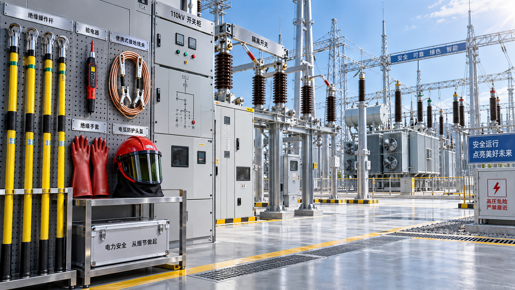
A properly selected Protable grounding and short-circuit assembly can create a temporary connection between the conductor and earth while providing a path for fault current. The assembly should be selected according to the expected fault duty, conductor arrangement, cable cross-section, required length, and clamp configuration. High-conductivity copper conductors support effective current discharge, while secure clamps and a durable insulated sheath help the assembly withstand field handling.
Grounding equipment is not “fit” simply because it is present. Check that clamps match the conductor or grounding point, contact surfaces are clean enough for reliable connection, cables have no damaged strands or insulation cuts, and the grounding point is known to be effective. Apply and remove the set in the approved sequence for the local work procedure. A loose clamp, a cable routed where it can be crushed, or an improvised earth point defeats the purpose of the control.
Personal protection must match the remaining exposure
Even with a sound isolation plan, maintenance work can involve uncertainty during testing, boundary checks, or access around adjacent energized equipment. PPE should therefore be chosen for the hazards that remain after engineering and procedural controls are in place. It should not be selected by appearance or used as a universal substitute for planning.
Gloves require more than a quick visual glance. Roll the cuff and inspect the full surface under good light. Any sticky area, discoloration, embedded debris, ozone cracking, or suspected puncture should remove the glove from service until it is evaluated under the applicable inspection process. Leather protectors can help guard insulating gloves from mechanical damage, but they must not conceal a compromised insulating layer.
Arc-rated clothing also needs a practical fit check. Sleeves that catch on panel hardware, face protection that fogs badly, or a hood that limits peripheral vision can encourage unsafe shortcuts. Workers should be able to move, see test points, operate controls, and communicate without defeating the protective arrangement. Loose jewelry, conductive watches, exposed metal accessories, and non-rated synthetic garments can create additional hazards and should be addressed before the work area is entered.
Inspect the tools that will touch the equipment
Insulated hand tools are often treated as ordinary tools with colored handles. Their insulation is a protective feature and must remain intact. Examine the coating for cuts, burns, separation, deep scratches, chemical damage, or exposed metal beyond the intended working end. A damaged insulated screwdriver should not be retained as a “low-voltage only” spare; once its insulating protection is compromised, its condition no longer supports that use.
Test instruments and leads deserve the same attention. Verify that meter leads are correctly rated for the intended measurement environment, probe tips are intact, shrouds are present where applicable, and lead insulation has no split or abrasion. Select the proper function and range before contacting the circuit. Connecting a meter set to resistance or current measurement across a voltage source can create an immediate fault condition.
For mechanical work, check torque tools, cable cutters, hydraulic devices, lifting equipment, and access equipment for the task-specific risks they introduce. A tool that is electrically safe may still cause injury if it slips, overloads a cable tray, damages a conductor, or forces the worker into an unstable posture. Good electrical maintenance safety equipment supports the work sequence; it does not remove the need to control mechanical hazards.
A field-ready release check before touching conductors
Just before work begins, pause at the work location rather than relying only on preparation completed elsewhere. Conditions can change between the planning discussion and the moment a panel door opens. The following questions are useful as a release check:
- Is the exact equipment identity confirmed? Labels, drawings, feeder names, and physical routing should agree. Stop if the identification is unclear.
- Have all energy sources been isolated and secured? Include control, backup, and interconnected sources, not only the main incoming supply.
- Has absence of voltage been verified at the work point? Use the approved test method and confirm that the tester itself is functional.
- Has stored or induced energy been addressed? Discharge where necessary, then apply temporary grounds or short-circuiting devices when the risk assessment requires them.
- Are boundaries still controlled? Barriers, signs, covers, and access restrictions should prevent unplanned entry into adjacent energized areas.
- Is every person protected for the actual task? Confirm PPE, tool condition, communication method, and the role of each person before conductors are handled.
This pause is especially important when work is handed over between shifts or when the task changes from inspection to repair. A condition that was safe for visual inspection may not be safe for disconnecting a cable, removing a cover, or reaching behind equipment.
Conditions that should stop the job
A stop-work decision is appropriate when a critical control cannot be verified. Examples include a voltage detector that does not prove correctly, missing isolation information, an unexpected energized indication, damaged gloves or test leads, a grounding clamp that will not make secure contact, standing water near the work area, unclear communication between team members, or an access route that places the worker within an unsafe approach distance.
Stopping does not mean abandoning the job; it means returning to the point where certainty was lost. Recheck drawings and labels, identify alternate sources, replace defective equipment, improve lighting or access, and revise the work boundary. Continuing with an assumption is rarely faster once rework, equipment damage, or injury risk is considered.
Care after the task protects the next maintenance crew
Safety equipment can degrade quietly between jobs. After use, remove temporary grounds in the approved order only after the work is complete and the system status is authorized to change. Clean insulating tools, gloves, mats, and face protection according to their care instructions. Allow wet equipment to dry properly, keep insulating surfaces away from oil and direct damage, and store grounding cables so that clamps and conductors are not crushed or sharply kinked.
Record defects immediately and separate unusable items from serviceable stock. A worn glove left in a general storage bin, a failed detector returned to a kit, or a grounding cable with hidden conductor damage can reach the next job unnoticed. Consistent inspection, controlled storage, and prompt replacement are what turn a collection of protective items into reliable maintenance protection.
Recommend
 Oct 25, 2026
Homemade Bird Repellent Spray: Recipe Limits and Outdoor Surface Risks
Searching for how to make homemade bird repellent spray? Discover recipe limits, outdoor surface risks, electrical safety tips, and safer deterrents before you spray.
- Oct 25, 2026
Natural Bird Deterrents for Rooftops: Choosing Nonchemical Options
Learn how to repel birds naturally with humane rooftop barriers and smarter maintenance. Compare nonchemical options to protect electrical equipment and keep roof access clear.
- Oct 24, 2026
Home Remedies for Repelling Birds: What to Try on Patios and Railings
Learn how to repel birds with home remedies for cleaner patios and railings. Discover humane DIY options, avoid harmful sprays, and keep deterrents clear of electrical equipment.