 English
 Español
 Português
 Français
 Deutsch
 русский
 한국어
한국어 にほんご
にほんご हिन्दी, हिंदी
 বাংলা
বাংলা Bahasa Indonesia
 Türkçe
 Việt
Việt dansk
dansk čeština
 עִבְרִית Ivrit
 Filipino/Pilipino
 български език (Bǎlgarski jazik)
 suomi
suomi norsk
norsk język polski
 ไทย
ไทย ກະຣຸນາ
 Bahasa Melayu
 ភាសាខ្មែរ
 ဗာရမ်
ဗာရမ် اردو
اردو فارسی
فارسی Italiano
 Nederlands
 svenska
 Монгол хэл
 नेपाली
 සිංහල
සිංහල Ўзбек тили
 پښتوتۆرکجه
 Ελληνικά
 српски / srpski
 magyar
 українська
 Kiswahili
 Қазақ тілі
 Română
 Hrvatski
 Bosanski
 Kreyòl ayisyen
 አማርኛ
አማርኛ Hausa
Hausa Yorùbá
 Igbo
IgboPower Plant Safety Equipment: Selection Criteria for High-Voltage Operations
High-voltage safety equipment should not be selected by nominal voltage alone. In power plants, substations, switchyards, renewable-energy collector stations, and industrial distribution facilities, the actual protection requirement is determined by the combination of system voltage, available fault current, switching configuration, induced-voltage exposure, environmental conditions, and the work method authorized by the operating procedure.
A product can carry an appropriate voltage label yet still be unsuitable for the task if its short-circuit withstand is not matched to the network, its clamps cannot make reliable contact with the installed conductors, or its insulation performance degrades under the site’s contamination and weather conditions. For technical evaluation, the central question is not whether a tool is “high-voltage rated,” but whether its verified performance supports a specific hazard-control function under defined operating conditions.
Start with the electrical duty, not the product category
“Power plant safety equipment” covers several different protective functions. Insulating tools prevent a worker from bridging an energized part to earth or another potential. Portable grounding and short-circuiting sets protect personnel after isolation by discharging trapped or induced voltage and, when correctly designed, creating an equipotential work zone if the circuit is inadvertently energized. Voltage detectors support the absence-of-voltage verification process. Arc-rated clothing, face protection, gloves, and footwear address exposure that remains possible during defined tasks.
These functions are complementary but not interchangeable. An insulating operating rod does not replace temporary earthing. A grounding set does not establish absence of voltage. Personal protective equipment does not compensate for a deficient isolation, lockout, or grounding procedure. Equipment evaluation should therefore begin with the site’s approved sequence of operations and identify where each item acts within that sequence.
For temporary grounding equipment, a meaningful duty definition should include:
- the highest system voltage and grounding arrangement;
- the maximum prospective short-circuit current at the intended application point;
- the clearing time of the relevant protective device;
- the possible sources of backfeed, induced voltage, capacitive charge, and distributed generation;
- the conductor geometry, busbar dimensions, terminal materials, and available earthing points;
- the physical work location relative to the grounding point and the isolation point.
The fault-current and clearing-time relationship is particularly important. A grounding assembly is exposed to thermal and electrodynamic stress during a fault, not merely to normal load current. Cable cross-section, conductor material, clamp design, ferrules, joints, and connection hardware must be assessed as one current path. Selecting a heavier-looking cable without verifying the complete assembly rating is not a valid engineering check.
Voltage rating must be interpreted with the operating method
For insulating equipment, voltage classification is meaningful only alongside the intended use. A tool used for live-line operations, a tool used inside a de-energized-but-not-yet-earthed enclosure, and a tool used to apply grounds from a safe position may require different insulation lengths, protective clearances, and handling characteristics.
Technical documentation should state the applicable voltage class or maximum use voltage, test voltage, test method, and relevant standard. It should also clarify whether the rating applies to the complete assembly or only to an individual component. Modular tools deserve added scrutiny because combining a head, extension section, adaptor, and operating pole can change the usable length, mechanical loading, and contamination exposure.
Nominal system voltage should not be used as a shortcut for minimum approach distance or required insulating length. Those values depend on local regulations, utility rules, work category, and the possibility of transient overvoltage. Equipment selection must align with the controlled work method, rather than allowing the presence of a tool rating to justify a work method that has not been assessed.
Portable grounding: the most consequential selection detail is often the connection point
Temporary earthing is frequently evaluated by cable size, while clamp compatibility receives less attention than it deserves. In service, connection integrity depends on the actual contact surfaces. Oxidized aluminum, painted steel, plated copper, weathered busbar, stranded conductors, and irregularly shaped terminals can all affect clamp engagement and contact resistance.
A clamp should be selected for the specific conductor or earth point, not for a generic “substation” application. The evaluation should verify jaw opening range, conductor profile compatibility, contact pressure, retention under vibration or accidental movement, and the ability to install and remove the clamp using the required insulated operating tool. A clamp that is difficult to position from the required distance invites unsafe improvisation.
Earth-end connection is equally important. A grounding set connected to an earthing point of uncertain integrity does not create dependable protection. The designated earth connection should be part of the site’s documented grounding system and accessible without exposing personnel to a different hazard. In some maintenance configurations, the location of the grounding set must also be considered against the possibility of backfeed from another source. A ground placed on only one side of a work area may not protect against an overlooked source on the other side.
Portable grounding and short-circuiting equipment intended for utility applications is commonly assessed against IEC 61230, which addresses portable equipment for earthing or earthing and short-circuiting. Conformity to that standard can be relevant evidence, but it does not remove the need to verify the stated short-circuit capability against the actual system study and installation arrangement.
Where line, busbar, switchgear, or transformer maintenance requires a configurable temporary earth, cable section, cable length, and clamp configuration should be specified against the installation rather than purchased as a standard kit. An assembly such as Protable grounding and short-circuit may be relevant where high-conductivity copper conductors, robust clamps, and IEC 61230 alignment are required, but its final suitability still depends on the calculated fault duty, installed connection points, and approved grounding procedure.
Environmental durability is a safety parameter
High-voltage equipment is routinely exposed to conditions that are more severe than the clean, controlled circumstances implied by many catalogue descriptions. Outdoor stations may combine ultraviolet exposure, rain, salt contamination, windborne dust, rapid temperature changes, and ice. Thermal stations and industrial plants may add oil mist, chemical deposits, abrasive dust, heat, and restricted access. Renewable-energy sites can introduce remote locations where storage and inspection discipline are harder to maintain.
For insulating tools, surface condition is crucial. Moisture and contamination can create leakage paths across an otherwise sound insulating surface. Material selection, surface finish, guard design, cleaning requirements, and storage arrangements should therefore be evaluated together. A tool that performs well electrically but cannot be kept clean or dry in its actual storage environment can become an operational weakness.
For grounding assemblies, the sheath must resist flexing, abrasion, and the environmental agents expected at the site, while remaining manageable in low temperatures. Cable stiffness is not merely a convenience issue: overly rigid assemblies can make secure routing and clamp placement difficult, particularly in compact switchgear rooms or at elevation. At the same time, flexibility should not be confused with reduced mechanical strength. The cable, termination, and clamp attachment must withstand normal field handling without exposing strands or weakening the current path.
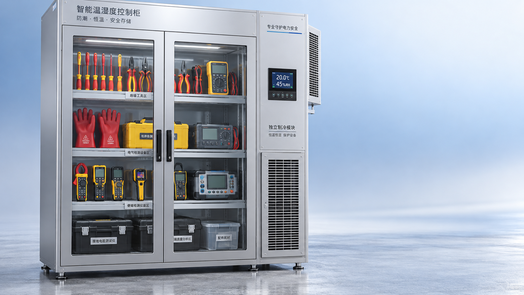
Environmental review should also include storage. Insulating poles stored against a damp wall, grounding leads dragged across sharp grating, and gloves left exposed to oils or sunlight can lose serviceability well before their scheduled test date. Procurement requirements should define suitable bags, cases, reels, or racks where the equipment type requires them.
Certificates are evidence, not a complete technical evaluation
Test reports, declarations of conformity, and third-party certificates are necessary inputs, but technical approval should examine what they actually cover. A certificate may apply to a product family, a particular configuration, or a sample tested under specified conditions. It may not automatically cover a custom cable length, a different clamp, a substituted connector, or a locally assembled kit.
The review should establish:
- the issuing body and the standard or test specification referenced;
- the exact model, configuration, voltage class, or fault-duty rating covered;
- whether the documentation applies to the finished assembly rather than separate components;
- the test date, report identification, and traceability to delivered items;
- any service restrictions, inspection intervals, or storage conditions stated by the manufacturer.
For imported equipment, terminology can obscure important differences. “Tested,” “certified,” “compliant,” and “approved” do not have identical meanings. The acceptance specification should require the documents needed by the plant’s safety management system and should avoid relying on unqualified marketing terms. Where local regulations impose additional obligations, those requirements take precedence over a general international claim.
Reliability depends on inspection design and maintainability
The best selection is not necessarily the item with the highest initial rating. It is the item whose condition can be reliably assessed throughout its service life. This makes inspectability a design criterion.
Grounding leads should permit clear visual inspection of cable sheath, terminations, clamps, ferrules, and connection hardware. Clamps should not conceal damage in areas that cannot be checked without disassembly. Serial identification or durable asset marking helps connect the physical item to its inspection record, test history, and retirement decision. For insulating tools, visible cracking, surface damage, contamination, moisture ingress, or damaged end fittings must be detectable before use.
Periodic electrical testing is important, but it should not be treated as a substitute for pre-use inspection. Damage can occur between test intervals. A scheduled test may confirm insulation performance under defined conditions; it does not prove that a clamp was correctly attached during a particular maintenance activity or that a cable has not been mechanically compromised since the last inspection.
Evaluation documents should distinguish between mandatory periodic tests, routine visual checks, functional verification, cleaning instructions, and retirement criteria. If replacement parts are allowed, the specification should identify which components may be replaced and whether re-testing of the finished assembly is required afterward. Uncontrolled substitution of clamps, cables, or adaptors can invalidate the original performance basis.
Compatibility with plant practice is often where otherwise sound equipment fails
High-voltage safety equipment must work with the physical plant and the operating documents already in use. A technically acceptable grounding set can be unsuitable if its clamps do not fit the disconnect contacts, if the operating pole cannot reach the intended point, or if the lead routing creates a trip hazard across an escape path. A voltage detector can be unsuitable if its indication method cannot be reliably interpreted within the local procedure or if the required proving arrangement is absent.
Before final approval, the equipment should be reviewed against drawings, equipment photographs, connection-point dimensions, access limitations, and the planned sequence for isolation, verification, discharge, grounding, and removal. For complex substations, the same equipment may require different configurations for busbar work, feeder work, cable compartments, and transformer bays. One universal set is often less defensible than a small number of clearly defined configurations tied to identified work locations.
Installation time also matters, but “quick installation” should not be interpreted as permission to reduce verification steps. The right objective is a connection method that can be performed consistently, from the required safe position, with controlled handling and unambiguous inspection of each connection.
A defensible acceptance decision
A robust selection record links the equipment to a defined hazard and duty. It should state the system location, voltage and fault-duty basis, applicable standards, conductor and earth-point compatibility, environmental limits, required inspection regime, documentation requirements, and approved configuration. This record becomes especially valuable when the plant is modified, a short-circuit study is updated, or a replacement supplier is considered.
The recurring selection error is treating electrical safety tools as generic consumables. In high-voltage operations, their protective value comes from a verified relationship between the tool, the network, the work location, and the operating procedure. When that relationship is documented, equipment choices become easier to defend—and far less likely to fail at the moment personnel depend on them.
Recommend
 Oct 25, 2026
Homemade Bird Repellent Spray: Recipe Limits and Outdoor Surface Risks
Searching for how to make homemade bird repellent spray? Discover recipe limits, outdoor surface risks, electrical safety tips, and safer deterrents before you spray.
- Oct 25, 2026
Natural Bird Deterrents for Rooftops: Choosing Nonchemical Options
Learn how to repel birds naturally with humane rooftop barriers and smarter maintenance. Compare nonchemical options to protect electrical equipment and keep roof access clear.
- Oct 24, 2026
Home Remedies for Repelling Birds: What to Try on Patios and Railings
Learn how to repel birds with home remedies for cleaner patios and railings. Discover humane DIY options, avoid harmful sprays, and keep deterrents clear of electrical equipment.