 English
 Español
 Português
 Français
 Deutsch
 русский
 한국어
한국어 にほんご
にほんご हिन्दी, हिंदी
 বাংলা
বাংলা Bahasa Indonesia
 Türkçe
 Việt
Việt dansk
dansk čeština
 עִבְרִית Ivrit
 Filipino/Pilipino
 български език (Bǎlgarski jazik)
 suomi
suomi norsk
norsk język polski
 ไทย
ไทย ກະຣຸນາ
 Bahasa Melayu
 ភាសាខ្មែរ
 ဗာရမ်
ဗာရမ် اردو
اردو فارسی
فارسی Italiano
 Nederlands
 svenska
 Монгол хэл
 नेपाली
 සිංහල
සිංහල Ўзбек тили
 پښتوتۆرکجه
 Ελληνικά
 српски / srpski
 magyar
 українська
 Kiswahili
 Қазақ тілі
 Română
 Hrvatski
 Bosanski
 Kreyòl ayisyen
 አማርኛ
አማርኛ Hausa
Hausa Yorùbá
 Igbo
IgboTemporary Grounding Equipment: Key Selection and Testing Requirements
During an outage, a circuit may appear isolated while still carrying induced voltage, trapped charge, backfeed energy, or the consequences of an unexpected switching operation. Temporary grounding equipment is the protective assembly intended to create an equipotential work zone and provide a low-impedance path for fault current while personnel are exposed to normally energized conductors or equipment.
The core selection rule is straightforward: the assembly must be suitable for the maximum prospective fault duty at its exact installation point, and every part of the installed path must be compatible with the conductor, grounding point, environmental conditions, and approved work procedure. A voltage rating alone is not enough. Technical evaluation should focus on short-circuit withstand, connection integrity, cable construction, installation sequence, and periodic verification.
Start with the actual grounding duty, not the nominal system voltage
Nominal voltage helps identify insulation clearances, operating tools, and equipment class, but it does not establish whether a portable grounding set can survive a fault. The decisive electrical question is the fault current that may flow through the temporary ground connection before upstream protection clears the fault.
This evaluation requires more than a single system short-circuit value from a network diagram. The value at the work location can change with source configuration, parallel feeds, transformer connections, distributed generation, and switching states. A grounding set used on a transmission structure may face a different duty from one used inside a substation bay or on a distribution feeder. The available fault current and clearing time must be evaluated together because thermal stress depends on both.
For each intended point of use, establish:
- maximum prospective fault current under the relevant network configuration;
- protective device clearing time, including any breaker operating and relay coordination delays that apply to the fault path;
- available sources of contribution, including alternate feeders, transformers, generators, and stored-energy systems where applicable;
- the number and location of grounding sets required by the approved work method;
- whether the set is intended only for grounding or also for short-circuiting phases together.
A cable that is physically easy to handle may still be undersized for the duty. Conversely, selecting a very large conductor without considering clamp geometry and worker handling can create installation problems that undermine safe use. The correct selection balances electrical withstand with practical installation, but electrical duty remains the limiting requirement.
Assess the complete current path
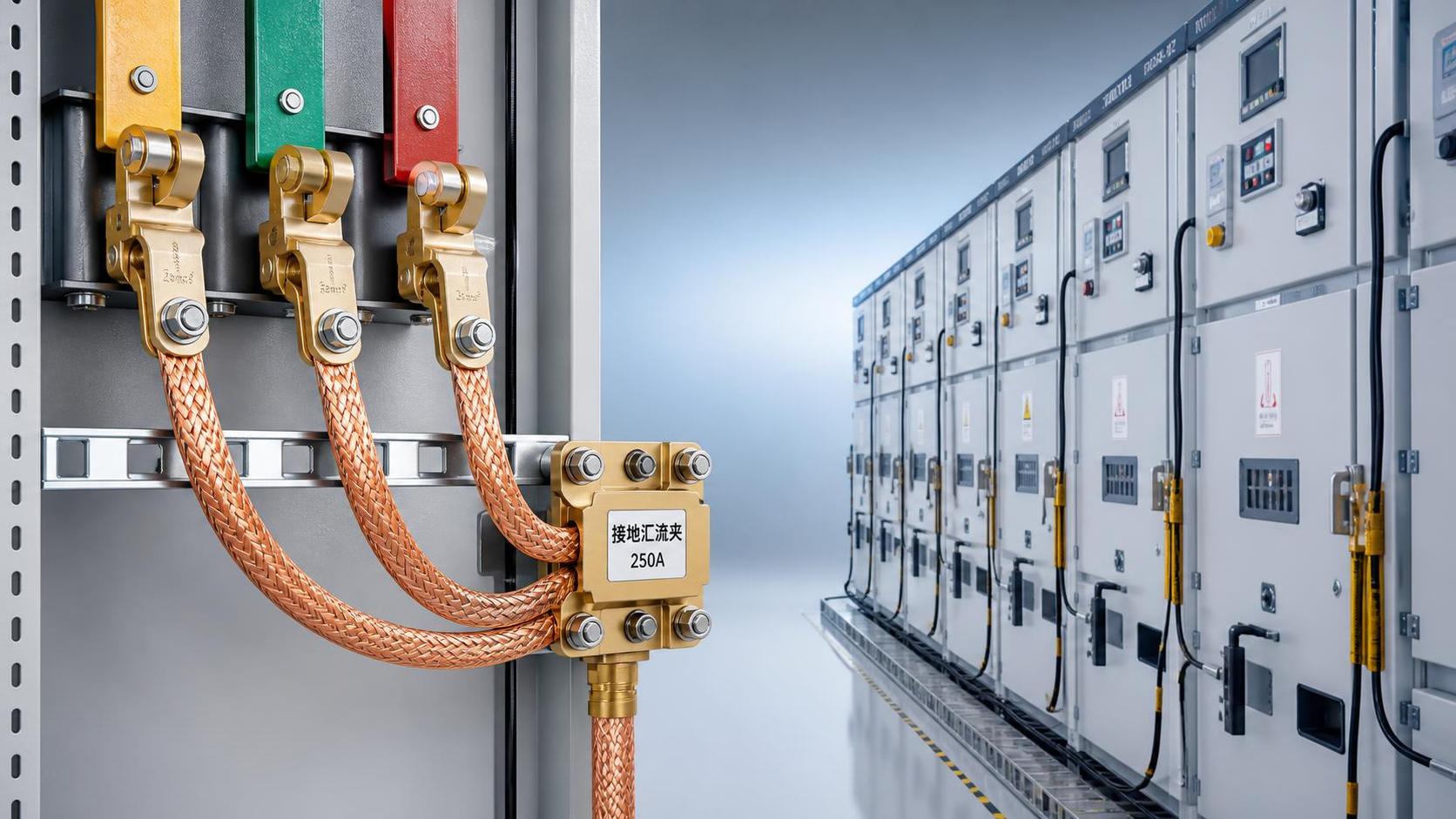
A temporary grounding assembly is only as capable as its weakest component. The cable, phase clamp, earth clamp, ferrules, connector hardware, grounding point, and mating conductor surface all form part of the fault-current path. Evaluating cable cross-section while treating the clamps as accessories is a common but serious error.
High-conductivity copper conductors are widely used because they provide low resistance and good flexibility for temporary installations. Yet conductor material alone does not confirm performance. Strand construction affects flexibility and fatigue resistance; terminations affect current transfer; and the protective sheath affects whether the conductor remains serviceable after repeated pulling, abrasion, moisture exposure, and field transport.
The grounding point deserves the same scrutiny as the assembly. A painted steel member, corroded fitting, loosely bonded structure, or point not verified as part of the grounding system should not be assumed to provide a reliable earth connection. The work procedure should identify approved connection points and confirm that they remain electrically and mechanically suitable.
Clamp selection is an installation-control issue
Grounding failures often begin with a mismatch between clamp design and the conductor or terminal actually encountered in the field. Round conductors, flat busbars, equipment studs, line hardware, and switchgear grounding provisions require different jaw shapes and operating arrangements. A clamp that can be forced onto a conductor is not necessarily one that makes adequate contact or resists movement.
Technical reviewers should examine the supported conductor diameter or busbar range, the jaw opening, the locking method, the contact surfaces, and the direction of mechanical load after installation. Where vibration, cable weight, wind movement, or restricted access may act on the assembly, the clamp must remain secure without relying on improvised support.
Clamps should also be evaluated for their ability to make contact through normal surface oxidation or contamination. This does not mean that damaged, heavily corroded, painted, or visibly dirty contact points are acceptable. Contact areas should be prepared according to the approved procedure, and clamp teeth or contact faces must be clean, sharp where designed to be sharp, and free from deformation.
For line and substation applications requiring a temporary earth and phase short-circuit arrangement, a product such as Protable grounding and short-circuit may be evaluated in relation to its available cable cross-sections, lengths, and clamp configurations. Its high-conductivity copper cable and strong clamp design address important elements of the current path, but acceptance still depends on matching the selected configuration to the calculated fault duty and the approved installation point.
Installation order protects against the moment of greatest exposure
The most hazardous moment may occur before the grounding set is fully connected. A safe system therefore needs a defined sequence, suitable operating tools, and verification that the circuit has been de-energized before temporary grounds are applied. The exact sequence must follow the governing safety rules and site procedure, but the general principle is consistent: establish the earth connection first, then connect to the conductors using an approved method. Removal is normally performed in the reverse order.
This sequence prevents a worker from handling an ungrounded assembly connected to a conductor that could unexpectedly become energized. It also ensures that any induced or residual voltage is directed to earth as soon as the phase connection is made.
- Review the isolation boundary, switching status, work location, and designated grounding points.
- Verify absence of voltage using the approved test method and correctly rated equipment.
- Inspect the grounding set before use, including cables, clamps, ferrules, locking parts, and operating attachments.
- Connect the earth end to the approved grounding point.
- Apply phase-end clamps in the required order using an appropriate insulating stick or other approved tool.
- Confirm that each clamp is fully seated, locked, and positioned so cable weight or movement cannot compromise contact.
- Before removal, confirm that personnel, tools, and work materials are clear, then remove phase connections before disconnecting the earth end.
Temporary grounding equipment is not a substitute for isolation, lockout, switching control, or voltage verification. It is an additional protective measure used after the prescribed controls have been applied. Treating portable grounds as the only barrier against energization is a procedural failure, even where the equipment itself is correctly selected.
Testing requirements should cover design qualification and continued serviceability
Equipment marked or supplied for IEC 61230 should be assessed against the applicable edition, scope, and product documentation. IEC 61230 addresses portable equipment for earthing or earthing and short-circuiting, but a technical review should not rely only on a reference printed on a label. Confirm which assembly configuration was qualified, including cable size, clamp type, connector arrangement, and intended duty.
Design and type verification commonly addresses electrical, thermal, mechanical, and functional properties. The precise test program depends on the applicable standard and product category, but the evidence should show that the assembly can carry the specified short-circuit current for the stated duration without unacceptable damage that would compromise its protective function. Mechanical tests are also relevant because clamps and terminations must withstand expected forces without loosening or separating.
For incoming evaluation, request clear identification of the assembly rather than generic test evidence for a related product family. Useful records include the model designation, cable cross-section, rated short-circuit current and duration, clamp configuration, standard reference, manufacturing traceability, and instructions for inspection and use. Any uncertainty between the tested configuration and the purchased configuration should be resolved before acceptance.
Routine inspection before each use
Pre-use inspection is not a simplified version of type testing. Its purpose is to identify damage that can develop between formal inspections. The person applying the grounds should look for cuts, crushed areas, heat marks, hardened or swollen sheath sections, exposed strands, corrosion, loose ferrules, distorted clamp jaws, weak springs, worn threads, and missing locking components.
Cable damage near a termination deserves particular attention. Repeated bending at this point can break strands internally while leaving the outer sheath mostly intact. A stiff or unusually flattened section may indicate internal damage. Ground sets that have been subjected to fault duty, severe mechanical loading, chemical contamination, or suspected overheating should be withdrawn from service until evaluated under the organization’s control process.
Periodic electrical and mechanical verification
A formal inspection interval should be defined by the asset owner’s safety program, applicable standards, manufacturer instructions, environmental exposure, and frequency of use. Sets stored in dry, controlled conditions may face different deterioration mechanisms from those repeatedly used outdoors, transported in service vehicles, or exposed to salt, industrial contamination, and UV radiation.
Continuity or resistance testing can help identify broken strands and defective terminations, but it must be interpreted carefully. A low-resistance reading does not prove that a clamp will remain mechanically secure or that the assembly will withstand its rated fault duty. Likewise, a visually clean cable does not prove sound electrical continuity. Effective maintenance combines documented visual examination, mechanical function checks, electrical continuity verification where specified, and removal criteria for damaged components.
Do not make unauthorized repairs to cable terminations, clamps, or connectors. Replacing a clamp or re-terminating a cable changes a component within the fault-current path. Unless the repair method, materials, tooling, and post-repair verification are controlled and approved, the original rating can no longer be assumed.
Watch for selection shortcuts that invalidate a compliant-looking set
A set can carry a standard reference and still be wrong for the intended work. The following shortcuts should trigger further review:
- using the same grounding set across locations with materially different fault levels;
- selecting by cable length and convenience before confirming short-circuit duty;
- assuming a larger clamp automatically fits every conductor or busbar arrangement;
- connecting to a structural member without confirmation that it is an approved grounding point;
- combining cables, clamps, or adapters from different assemblies without documented compatibility;
- continuing to use equipment after a fault event because no external damage is immediately visible;
- treating induced-voltage control on long parallel lines as identical to grounding a compact switchgear section.
Long parallel transmission or distribution conductors can develop induced voltage even after isolation. In those locations, grounding placement, bonding arrangement, conductor separation, and the work zone configuration require careful engineering review. The objective is not simply to attach a ground somewhere on the circuit; it is to keep workers within a controlled equipotential zone under credible induced-voltage and accidental-energization conditions.
Document the decision so the field team receives a usable assembly
The final selection record should state the work application rather than only a purchase description. It should identify the circuit or equipment category, maximum fault duty and clearing time used for selection, required cable length, phase and earth clamp types, approved grounding points, applicable standard basis, inspection status, and any installation restrictions. This prevents a correctly rated assembly from being deployed in an unintended configuration.
Where the network fault study, protective clearing time, or grounding-point integrity is uncertain, that uncertainty must be resolved before work begins. Temporary grounding is a critical protective control, and its rating cannot be established safely through visual similarity, nominal voltage, or prior habit alone.
Recommend
 Oct 26, 2026
Does Grape Kool-Aid Repel Birds? Evidence and Risks for Garden Use
Does grape Kool Aid repel birds? Explore the evidence, plant and wildlife risks, and more reliable garden protection options. Find out what works before you spray.
- Oct 26, 2026
How to Hang Bird Repellent Tape on Roof Edges Without Loose Strips
Learn how to hang bird repellent tape on roof edges without loose strips. Get practical tips on secure mounts, spacing, and electrical safety for a cleaner, safer installation.
- Oct 25, 2026
Homemade Bird Repellent Spray: Recipe Limits and Outdoor Surface Risks
Searching for how to make homemade bird repellent spray? Discover recipe limits, outdoor surface risks, electrical safety tips, and safer deterrents before you spray.