
 English
 Español
 Português
 Français
 Deutsch
 русский
 한국어
 にほんご
 हिन्दी, हिंदी
 বাংলা
 Bahasa Indonesia
 Türkçe
 Việt
 dansk
 čeština
 עִבְרִית Ivrit
 Filipino/Pilipino
 български език (Bǎlgarski jazik)
 suomi
 norsk
 język polski
 ไทย
 ກະຣຸນາ
 Bahasa Melayu
 ភាសាខ្មែរ
 ဗာရမ်
 اردو
 فارسی
 Italiano
 Nederlands
 svenska
 Монгол хэл
 नेपाली
 සිංහල
 Ўзбек тили
 پښتوتۆرکجه
 Ελληνικά
 српски / srpski
 magyar
 українська
 Kiswahili
 Қазақ тілі
 Română
 Hrvatski
 Bosanski
 Kreyòl ayisyen
 አማርኛ
 Hausa
 Yorùbá
 Igbo
‹
›
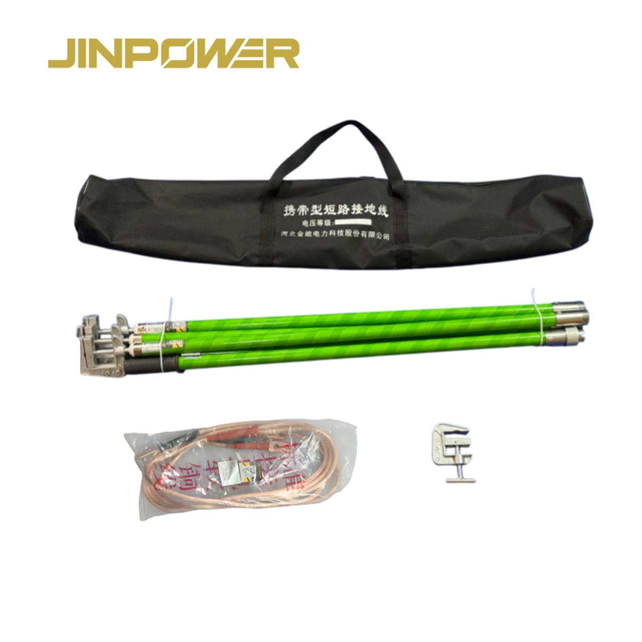
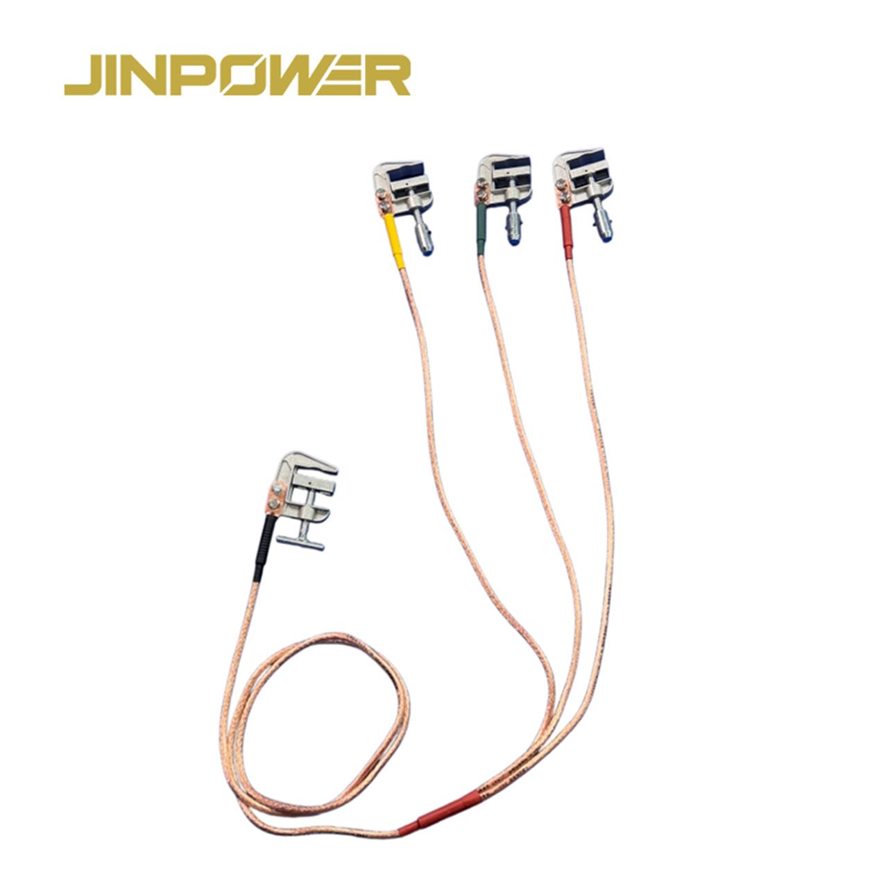
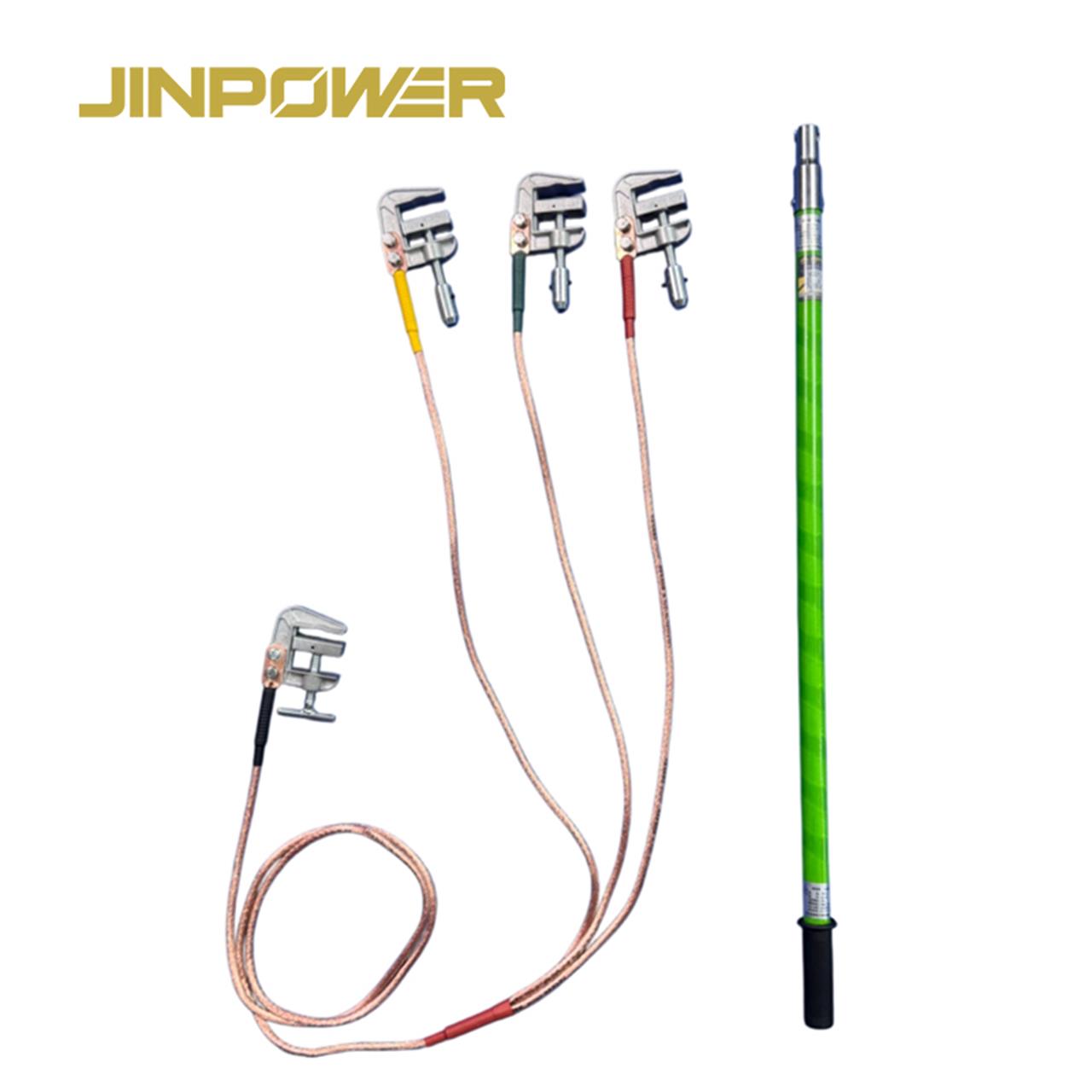
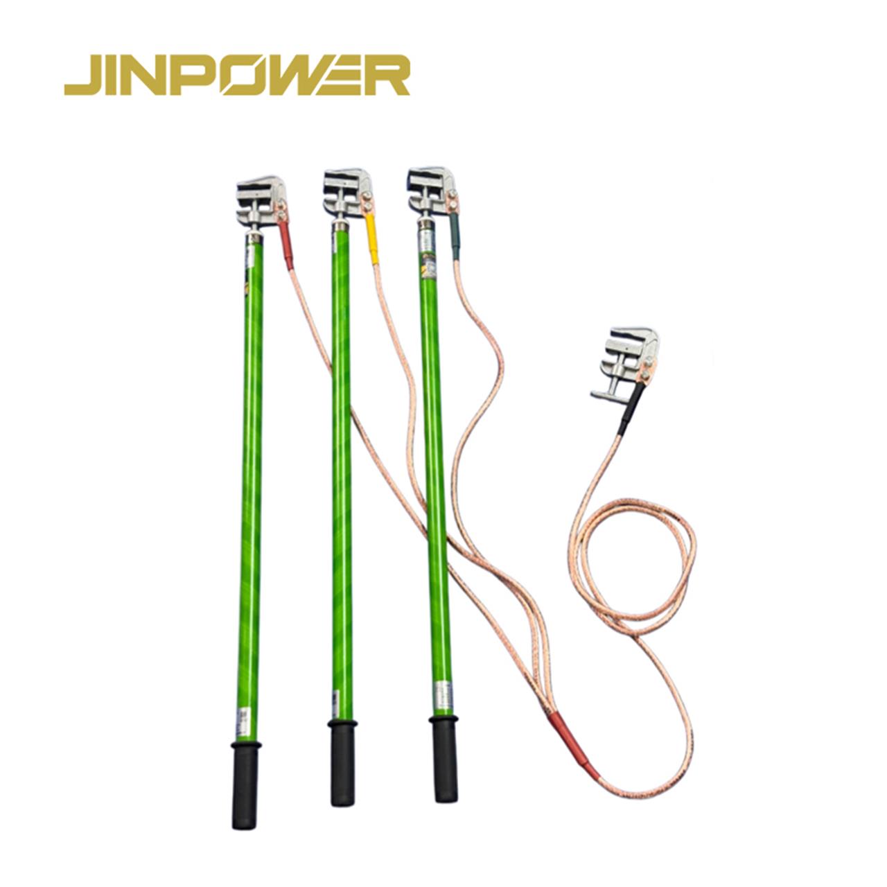
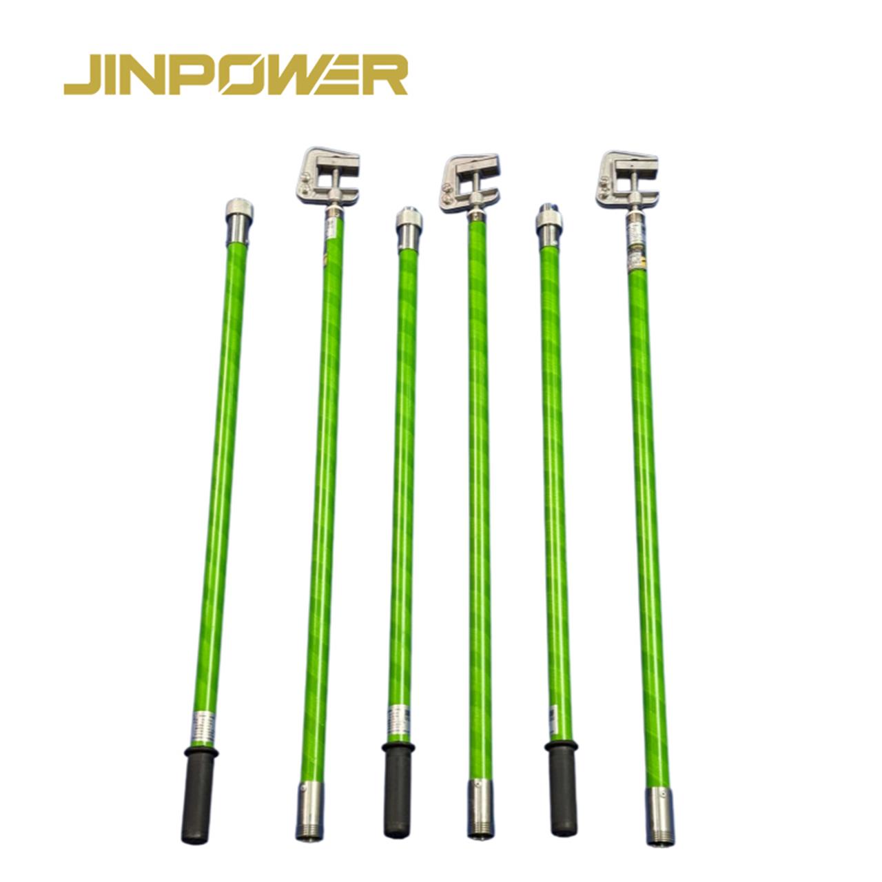
C-Type Screw-Operated Flat-Jaw Earthing Rod
JINPOWER supplies portable earthing rods with C-type screw-operated flat-jaw clamps for specified temporary earthing and short-circuiting applications. The flat-jaw design is intended for busbars and other conductive connection points with suitable flat or square contact surfaces.
The screw-operated mechanism allows the clamp to be tightened around a compatible connection point. Correct selection depends on the conductor dimensions, available clamp opening, contact geometry and the requirements of the complete earthing assembly.
Both telescopic and non-telescopic rod configurations can be considered according to project requirements. For utilities, electrical contractors, equipment distributors and project buyers, the key specifications include clamp dimensions, rod length, grounding cable configuration and the rated electrical performance of the selected assembly.
All Products
Stay Connected
If you have any questions, please contact us and we will contact you as soon as possible.
Prduct Introdution
Quick Product Facts
- Product Type: Portable Earthing Rod
- Clamp Type: C-Type Screw-Operated Flat-Jaw Phase Clamp
- Jaw Design: Flat Contact Surface
- Clamping Mechanism: Screw-Operated
- Rod Configurations: Telescopic and Non-Telescopic
- Typical Connection Points: Busbars and Compatible Flat or Square Conductive Surfaces
- Main Selection Factors: Clamp Opening, Conductor Dimensions, Rod Length and Electrical Ratings
- Application: Specified Temporary Earthing and Short-Circuiting
Technical Specifications
The following specifications cover the main information required for product selection and procurement. Exact dimensions, materials and electrical ratings should be confirmed against the selected model's technical datasheet and approved configuration.
For an accurate quotation, provide the conductor dimensions, required clamp opening, rod length, rod structure, grounding cable requirements and applicable electrical ratings. These details help confirm whether the selected configuration matches the intended installation.
Telescopic vs Non-Telescopic Earthing Rod
The C-type screw-operated flat-jaw clamp can be specified with different rod structures where both configurations are available for the selected product. The choice depends on the required operating reach, available working space, transport dimensions and project specifications.
When to Choose a Non-Telescopic Rod
A non-telescopic rod may suit projects that specify a fixed operating length. Buyers should confirm the total rod length, connection-point access and handling requirements before selecting this configuration.
When to Choose a Telescopic Rod
A telescopic rod may suit applications where an extendable structure helps meet the required operating reach and transport dimensions. Confirm the extended length, retracted length, number of sections and locking mechanism against the actual model specification.
The rod structure alone does not establish electrical performance. Both versions must meet the applicable electrical ratings and insulation requirements for the intended application.
C-Type Screw-Operated Flat-Jaw Clamp Design
The defining feature of this product is the combination of a C-type clamp body, a flat-jaw contact design and a screw-operated clamping mechanism. These features distinguish it from clamps designed primarily for round conductors or quick-release connections.
Flat-Jaw Contact Surface
The flat-jaw configuration is intended for compatible flat contact surfaces, including suitable busbars and other conductive components with matching dimensions. The contact geometry should fit the actual connection point.
A flat jaw is not automatically suitable for every flat or square conductor. The clamp opening, contact dimensions and permitted conductor range must be checked against the product specification before ordering.
Screw-Operated Clamping Mechanism
The screw mechanism is used to tighten the clamp around the compatible connection point. This allows the operator to adjust the clamping position according to the clamp design and the approved operating procedure.
The actual operating method, permitted tightening procedure and any torque requirements should follow the manufacturer's instructions. Do not assume that applying additional force improves electrical performance or connection reliability.
C-Type Clamp Structure
The C-type body provides the overall clamp structure around the connection point. Its dimensions and opening geometry determine which conductor profiles can be accommodated.
When evaluating a product for a specific busbar or conductive component, review the available clearance, conductor thickness, contact width and required clamp opening. A dimensional drawing can help confirm compatibility before procurement.
Connection to the Insulating Rod
The clamp connects to the operating rod as part of the selected earthing assembly. The connection interface, rod structure and supplied components should be confirmed from the actual model documentation.
If a project specifies a particular rod length or clamp connection arrangement, provide the relevant drawing or technical requirements when requesting a quotation.
Typical Applications of Flat-Jaw Earthing Clamps
Busbar Connections
Busbars are common conductive components in electrical distribution equipment and substations. Where the contact surface and dimensions are compatible, a flat-jaw clamp may be considered for the specified temporary earthing arrangement.
Selection should account for busbar thickness, contact width, available clearance and the required electrical rating of the complete assembly. Confirm the actual connection geometry before choosing the clamp.
Substation Electrical Equipment
Substations contain different conductor arrangements, busbars and electrical connection points. A flat-jaw clamp may be suitable where the designated connection surface matches the clamp dimensions and the product is rated for the intended application.
The installation drawing and approved work procedure should determine the required connection point and configuration. Do not select a clamp based only on its external appearance.
Electrical Distribution Installations
Distribution installations may use conductive bars and other connection components with different cross-sectional dimensions. The flat-jaw configuration should be considered only where its opening range and contact geometry match the intended connection.
For non-standard connection points, provide a photograph, drawing or dimensional sketch to support the compatibility review.
Temporary Earthing and Short-Circuiting
A flat-jaw phase clamp may form part of a temporary earthing and short-circuiting assembly when the complete configuration is suitable for the installation and its specified electrical duty.
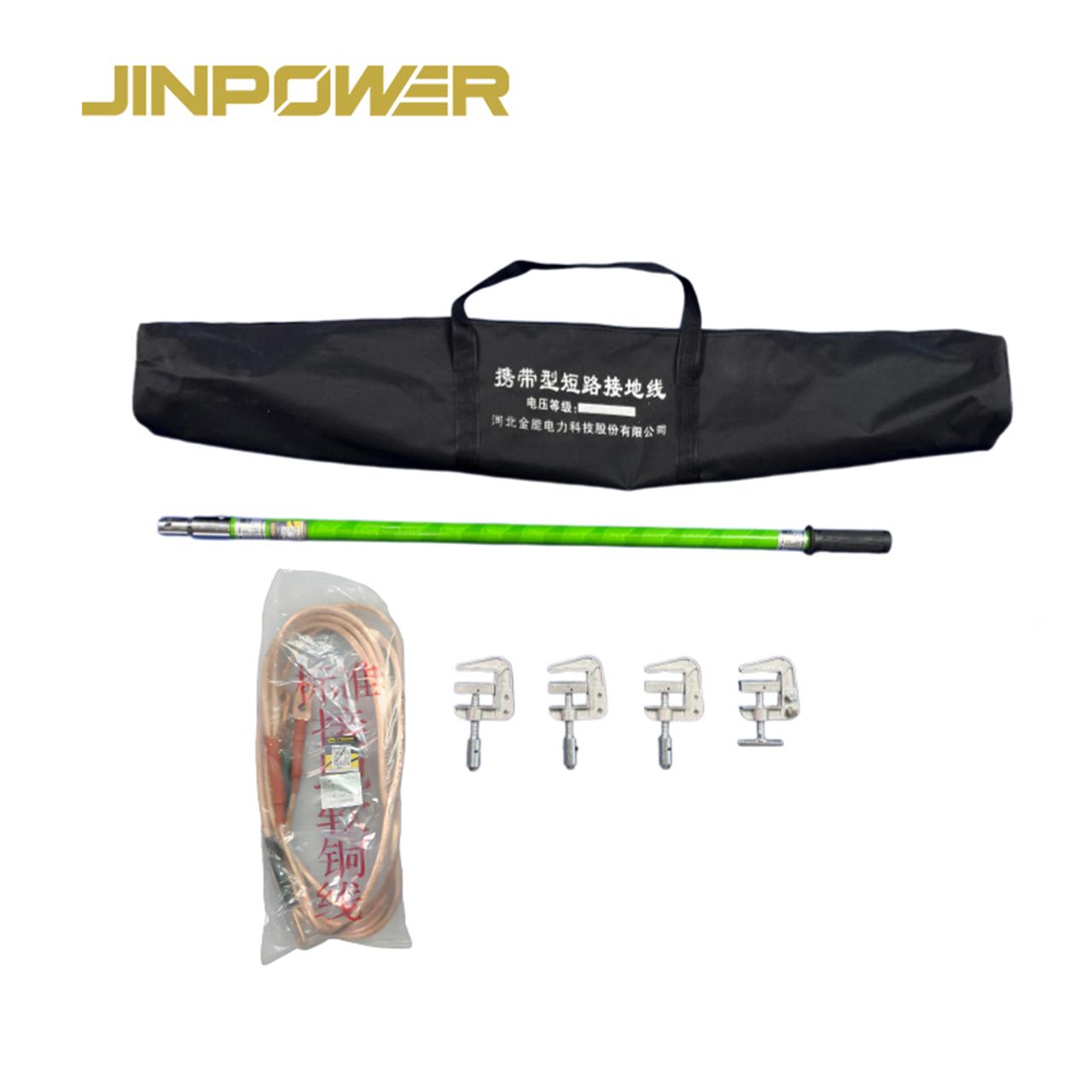
Confirm whether the order covers the operating rod and phase clamp only or a complete set including grounding conductors, grounding clamps and other required components. The supplied scope should match the project specification.
How to Select the Right Flat-Jaw Earthing Rod
1. Identify the Connection Surface
Identify the busbar or conductive component where the clamp will be applied. Record the contact surface shape, thickness, width and any restrictions around the connection point.
These details help determine whether a flat-jaw design is appropriate or whether another clamp configuration should be considered.
2. Confirm the Clamp Opening Range
Check the required opening against the clamp's specified operating range. The clamp must fit the intended connection point without exceeding its permitted dimensions.
If the clamp opening or contact dimensions are not available in the datasheet, request confirmation from the supplier before approving the configuration.
3. Review the Screw Mechanism
Confirm the actual screw-operated design and follow the manufacturer's operating instructions. For project-specific applications, identify any required tightening procedure or mechanical inspection criteria.
Do not use an assumed tightening torque or an improvised operating method in place of the approved product instructions.
4. Select the Rod Structure and Length
Choose between the telescopic and non-telescopic configurations according to the required operating reach, access conditions and transport dimensions.
For telescopic models, confirm the extended length, retracted length, section count and locking mechanism. For fixed-length models, confirm the overall length and the required working arrangement.
5. Confirm the Electrical Ratings
Check the rated short-circuit current, short-circuit duration and applicable insulation requirements of the complete earthing assembly. These parameters must match the project's electrical requirements.
The clamp's mechanical dimensions alone do not establish its suitability for a particular short-circuit duty. Request the applicable technical documents before approving the product.
6. Confirm the Grounding Cable Configuration
Identify whether the grounding cable is included in the ordered assembly. If required, specify the cable length, conductor cross-section, connection details and other project requirements.
The cable and clamp assembly must be compatible with the intended application and the electrical rating of the complete system.
7. Review Drawings and Test Documentation
For project procurement, confirm the required dimensional drawing, technical datasheet, applicable electrical test records and product identification. Verify that the documents correspond to the exact model and assembly being supplied.
Electrical Ratings and Product Compatibility
The mechanical connection and electrical rating are separate selection considerations. A clamp may fit the conductor dimensions but still be unsuitable if the complete earthing assembly does not meet the required electrical duty.
Conductor Compatibility
The flat-jaw clamp should match the actual contact geometry and dimensions. Confirm the conductor thickness, contact width and clamp opening range against the approved specification.
Rated Short-Circuit Current and Duration
Temporary earthing and short-circuiting equipment must be selected according to the required fault-current conditions. The rated short-circuit current and permitted duration should be supported by the applicable product documentation.
Do not assume that clamps with similar dimensions or materials have the same short-circuit performance. Confirm the rating of the complete assembly rather than evaluating the clamp in isolation.
Insulating Rod Requirements
The rod's insulating performance must be supported by the technical specification and applicable test requirements for the selected model. Total rod length alone does not establish its electrical suitability.
For telescopic versions, verify the requirements applicable to the complete rod and its approved operating configuration.
Quality Inspection and Technical Documentation
For utility, contractor and distributor orders, inspection should cover the mechanical configuration and the electrical requirements specified for the product. The inspection plan should be agreed according to the selected model, applicable requirements and project acceptance criteria.
Mechanical Inspection
Mechanical inspection may include checking the clamp body, jaw surfaces, screw mechanism, rod dimensions and supplied connection components. Any dimensional acceptance criteria should follow the approved drawing or specification.
Electrical Performance Verification
Where required, confirm the applicable electrical performance tests and supporting records for the selected assembly. Visual inspection and mechanical operation checks alone do not establish the product's electrical suitability.
Documentation for Project Acceptance
Depending on the project, required documents may include a technical datasheet, dimensional drawing, electrical ratings, applicable test reports and inspection records. Confirm the available documents and their scope before order approval.
Safety Requirements for Temporary Earthing
Portable earthing equipment must be selected and used by trained and authorized personnel in accordance with the equipment manufacturer's instructions, applicable electrical safety requirements and the approved site procedure.
Isolation and Voltage Verification
Disconnection alone does not establish that electrical equipment is safe. Required isolation and voltage verification must be completed using the approved procedure and suitable equipment before the relevant work proceeds.
Where voltage detection is required, see our High Voltage Detector range for related electrical safety equipment.
Correct Clamp Application
Use the clamp only on connection points compatible with its dimensions and approved application. Follow the manufacturer's instructions for operating the screw mechanism and applying the complete earthing assembly.
Do not assume that a mechanically secure connection is sufficient if the assembly's electrical rating has not been verified.
Inspection Before Use
Inspect the clamp body, jaw surfaces, screw mechanism, insulating rod and any supplied grounding components according to the manufacturer's instructions. Remove damaged or defective equipment from service until it has been evaluated by qualified personnel.
This product description does not imply suitability for live-line contact. Use the equipment only within its approved application and the applicable electrical safety procedure.
Related Grounding and Electrical Safety Products
Depending on your project requirements, JINPOWER also supplies related grounding equipment and components for specified electrical safety applications.
- Portable Earthing and Short-Circuiting Set — for projects requiring a complete temporary earthing and short-circuiting assembly.
- Grounding Cable — for grounding cable specifications and compatible connection requirements.
- High Voltage Detector — for voltage verification as part of an approved electrical safety procedure.
What Should You Include in Your RFQ?
Providing the technical details at the inquiry stage helps reduce specification gaps and unnecessary quotation revisions. For project orders, include the conductor dimensions and the electrical requirements of the complete earthing assembly.
If the connection point has non-standard dimensions, include a drawing or photograph with the inquiry. This helps the technical team review the required clamp configuration before quotation and order confirmation.
Frequently Asked Questions
What is a C-Type Screw-Operated Flat-Jaw Earthing Rod?
It is a portable earthing rod fitted with a C-type clamp that uses a flat-jaw contact design and a screw-operated clamping mechanism. It is intended for specified temporary earthing applications where the connection geometry and electrical ratings are compatible with the selected assembly.
What is the main purpose of the flat-jaw design?
The flat-jaw design is intended for compatible flat contact surfaces, including suitable busbars and other conductive components. The actual conductor dimensions and clamp opening must be checked before selection.
How does the screw-operated mechanism work?
The screw mechanism is used to tighten the clamp around the intended connection point. The operating method and any tightening requirements should follow the manufacturer's instructions for the selected model.
Can this clamp be used on every type of busbar?
No. Suitability depends on the busbar dimensions, contact geometry, clamp opening and the electrical requirements of the complete assembly. Confirm compatibility using the technical specification or an approved drawing.
What is the difference between telescopic and non-telescopic versions?
A non-telescopic rod has a fixed-length structure, while a telescopic rod uses extendable sections. Select the configuration according to the required operating reach, transport dimensions and actual product specifications.
Is the grounding cable included?
The supplied components depend on the ordered configuration. Confirm whether the quotation covers the rod and clamp only or a complete assembly with grounding cable, grounding clamps and other required accessories.
What electrical ratings should I confirm before purchasing?
Confirm the rated short-circuit current, short-circuit duration, applicable insulation requirements and other parameters specified by the project. The ratings must be supported by the technical documentation for the selected assembly.
Can the clamp be used for live-line work?
Do not assume that this product is suitable for live-line applications. Use it only within its explicitly approved application and follow the applicable electrical safety procedure and manufacturer's instructions.
What documents should I request before bulk purchasing?
Depending on the project, request the technical datasheet, approved drawing, electrical ratings and applicable test or inspection records. Confirm that the documents correspond to the exact model and assembly being supplied.
What information is needed for a quotation?
Provide the conductor dimensions, required clamp opening, rod structure, required length, grounding cable requirements, electrical ratings, quantity and project standards. A drawing or photograph of the connection point is also useful when available.
Request a Quote for C-Type Flat-Jaw Earthing Rods
If you are sourcing C-type screw-operated flat-jaw earthing rods for busbars, substations or other specified temporary earthing applications, contact JINPOWER with your project requirements.
Please provide the required rod structure, overall length, conductor dimensions, clamp opening, grounding cable configuration, rated short-circuit current and duration, and applicable project requirements.
For non-standard connection points, include a dimensional drawing or photograph to help clarify the required clamp configuration. JINPOWER can review the requested specifications and available technical documentation before quotation and order confirmation.
Inquiry