English
 Español
 Português
 Français
 Deutsch
 русский
 한국어
 にほんご
 हिन्दी, हिंदी
 বাংলা
 Bahasa Indonesia
 Türkçe
 Việt
 dansk
 čeština
 עִבְרִית Ivrit
 Filipino/Pilipino
 български език (Bǎlgarski jazik)
 suomi
 norsk
 język polski
 ไทย
 ກະຣຸນາ
 Bahasa Melayu
 ភាសាខ្មែរ
 ဗာရမ်
 اردو
 فارسی
 Italiano
 Nederlands
 svenska
 Монгол хэл
 नेपाली
 සිංහල
 Ўзбек тили
 پښتوتۆرکجه
 Ελληνικά
 српски / srpski
 magyar
 українська
 Kiswahili
 Қазақ тілі
 Română
 Hrvatski
 Bosanski
 Kreyòl ayisyen
 አማርኛ
 Hausa
 Yorùbá
 Igbo
How Do You Assess Wind Resistance in Outdoor Barrier Stands?
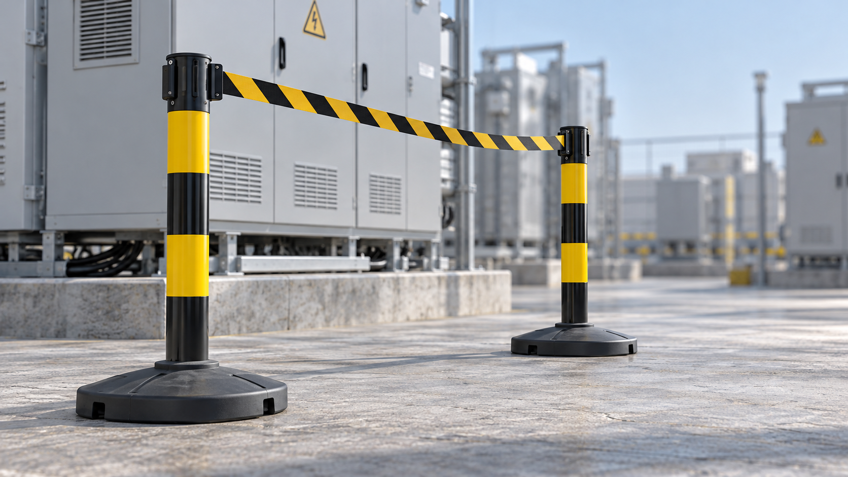
A heavy base does not automatically make an outdoor barrier stable in wind. A lighter stand with a wider footprint and a small exposed barrier can perform better than a heavier stand carrying a large sign. Assessing outdoor barrier stand wind resistance means evaluating the complete assembly: its base, post, belt or panel, connections, ground contact, and exposure to gusts.
The most useful comparison is between documented configurations under defined conditions. A wind-speed claim has limited value unless it identifies what was attached, how the base was secured, and what counted as failure. For an electrical work area, stability also means keeping the boundary in its intended position without allowing loose components to enter nearby equipment or access routes.
Compare the complete barrier, not just the stand weight
Wind pushes against the surfaces exposed to it. That force can slide the base, overturn the stand, bend the post, or pull connections apart. These are different failure modes, and improving one does not necessarily solve the others.
A broad base generally provides more resistance to overturning because the stand must rotate around its outer edge before falling. Keeping weight low also helps. Sliding, however, depends heavily on the interaction between the base and the ground. A wide, heavy base may still move across a slippery surface.
The height of the wind load matters as much as its size. A sign attached near the top of a post creates more overturning force than the same sign mounted lower down. This explains why two assemblies using identical bases can behave differently.
No configuration wins in every setting. A stand moved repeatedly during short maintenance tasks has different practical requirements from a barrier left around an exposed work area overnight. Compare the options against the intended installation and relocation pattern.
The belt, chain, or panel can change the result
A narrow chain usually presents less projected area to wind than a solid panel of similar overall dimensions. Mesh allows some airflow, but its loading depends on the openness, material, shape, and supporting frame. A product described as “mesh” should not automatically be treated as having negligible wind resistance.
Retractable belts introduce another consideration: the extended span. Wind can make the belt flutter and apply changing forces to the posts and connections. The effect depends on belt width, extension, tension, and orientation. A stability claim for a bare stand does not establish performance with a belt fully extended.
Solid signs and privacy screens deserve particular attention. They add exposed area and may place the resulting force high above the base. Adding a warning board to an existing stand therefore changes the assembly, even if the board appears lightweight.
Linked barriers also behave as a system. Connections may share loads, but they can also transfer movement from one stand to the next. A long straight run, a corner, and a closed enclosure do not necessarily respond alike. Do not assume that connecting more stands always improves stability. The layout and connections need to support that conclusion.
How to judge a supplier’s wind-resistance claim
“Suitable for outdoor use” may describe weather-resistant materials without establishing stability in strong winds. Corrosion resistance, UV durability, and wind resistance address different performance questions.
A useful wind-performance statement should identify the configuration and conditions behind it. When comparing suppliers, request the following information:
- Assembly details: base type, post height, barrier material, extension length, attachments, and layout.
- Ballast or anchoring: the installed mass, its location, and any required fixing arrangement.
- Test surface: the surface material, slope, condition, and whether the base was restrained.
- Wind exposure: direction, duration, and whether the stated speed represents steady flow or gust conditions.
- Acceptance criteria: whether sliding, rocking, excessive deflection, connection release, and overturning were assessed.
- Evidence: a test report or engineering assessment tied to the supplied configuration.
These details explain whether two apparently similar ratings are comparable. One assembly might remain upright while sliding far enough to leave a work boundary open. Another might keep its bases in place while a belt releases. Neither outcome is adequately described by “did not tip over.”
Also distinguish a test result from an operating limit. Surviving a particular test does not, by itself, define a suitable maximum wind speed for routine use. An operating limit needs to account for the intended conditions, variability, and the margin applied in the assessment.
If the proposed installation differs from the documented arrangement, identify the difference before selecting it. A taller post, longer span, added sign, or alternative base can change the load path and invalidate a direct comparison.
Why gusts and site exposure matter
Wind force increases approximately with the square of wind speed when the other relevant conditions remain unchanged. Doubling wind speed can therefore produce roughly four times the aerodynamic force. This relationship explains why a modest-looking increase in wind speed can cause a substantial change in stability.
Gusts add sudden loading, and changing wind direction can expose a different face of a panel or base. A barrier that appears steady during a brief observation may still be unsuitable for the strongest conditions expected during its deployment.
Assess exposure at the barrier’s actual location. Building corners, gaps between structures, open yards, and elevated positions can produce conditions different from those suggested by a general weather forecast. Nearby structures may shelter one section while directing stronger airflow toward another.
Use forecasts to plan the work and local observations or measurements to assess conditions at the installation. Compare wind information on a consistent basis: a reported average speed and a short-duration gust are different measures. A handheld reading taken during a quiet interval should not be treated as the maximum expected exposure.
The deployment period matters too. A boundary supervised continuously during a short task offers opportunities to respond to changing conditions. An unattended installation needs an arrangement suitable for the conditions that may develop before the next inspection.
Ground conditions can reverse the comparison
A base that performs well on level, dry concrete may behave differently on wet paving, gravel, mud, or a sloping surface. Friction changes, and the base may lose even support. On soft ground, one side can settle and leave the post leaning before significant wind arrives.
Look for rocking, gaps beneath the base, loose aggregate, standing water, and surface contamination. A textured or rubber contact surface may improve grip in suitable conditions, but it does not establish performance on every substrate. Ice, mud, wear, or trapped debris can change the contact considerably.
Slopes require particular care because gravity already encourages movement downhill and alters the stand’s position relative to its supporting edge. Adding weight without addressing the slope may increase handling difficulty without producing an acceptable installation.
Choose a level, sound location where possible. If the base cannot sit as intended, relocate the boundary or use a support arrangement designed for the surface. Improvised packing can introduce unstable contact and should not be treated as equivalent to a suitable foundation.
Extra ballast or anchors: which addresses the problem?
Ballast is useful when the stand and base are designed to accept it securely. It can increase resistance to overturning and may improve sliding resistance by increasing contact force. Its effectiveness still depends on placement and ground conditions.
Weights positioned low and within the intended base arrangement generally contribute more predictably than loose objects stacked around a post. Ballast must remain in position during movement and vibration. It should not obstruct an escape route or create a new trip hazard.
Fillable bases need the specified filling arrangement. Water and granular materials behave differently, and fill choice affects handling, leakage, and temperature suitability. The relevant performance is that of the filled assembly as installed, not the empty base’s appearance or capacity alone.
Anchoring is appropriate when loads need to be transferred into a suitable supporting structure or ground system. The post, fixing bracket, anchor, and substrate all become part of the load path. Strength at one connection cannot compensate for weakness elsewhere.
Drilling or driving stakes at electrical sites also requires attention to buried services, earthing conductors, and restrictions on ground disturbance. Attaching restraints to nearby equipment or structures without an approved arrangement can introduce additional hazards. Where ballast remains inadequate and suitable anchoring is unavailable, changing the barrier type or relocating the boundary may be the practical solution.
Keep wind stability separate from electrical protection
A stable barrier helps preserve a visible boundary, but wind resistance does not establish electrical insulating performance. A plastic post or coated metal component should not be assumed suitable for electrical contact because of its appearance.
Review the complete assembly against the site’s electrical safety requirements, including bases, chains, signs, fixings, and any added ballast. Required approach distances must remain effective if a belt bows, a post deflects, or a component moves within its permitted range.
This is especially relevant when changing attachments to reduce wind loading. A more open barrier may reduce exposed area, but it must still provide the visibility and access control required for the task. Wind performance and boundary function need to be satisfied together.
Make the selection usable on site
Before purchase, define the intended height, span, attachments, surface, layout, and exposure. Use those conditions to compare documented assemblies. This produces a more useful shortlist than comparing base weights or isolated wind-speed figures.
Before deployment, inspect bases, posts, locks, belts, and connectors for damage or wear. Confirm that ballast and anchors match the selected arrangement and that the installed boundary leaves adequate clearance around the hazard. Pushing a post by hand may reveal looseness or rocking, but it does not reproduce distributed wind loads or establish a wind rating.
Set a clear response for deteriorating conditions: who monitors the installation, what triggers intervention, and how an effective boundary will be maintained during adjustment or removal. Reassess after relocation, attachment changes, heavy rain, ground softening, or visible movement.
The strongest purchasing decision is a stand whose documented configuration matches the site and whose operating limits can be followed in practice. Start with the complete assembly and its evidence; use weight, footprint, ballast, and anchoring to explain why that arrangement suits the job.
Next:No more content
Recommend
 Oct 29, 2026
How Do You Assess Wind Resistance in Outdoor Barrier Stands?
Assess outdoor barrier stand wind resistance with practical tips on bases, ballast, anchors, and gust exposure. Learn how to compare supplier claims and choose the right setup for your site.
- Oct 29, 2026
Wall-Mounted vs. Freestanding Barriers: Which Should You Choose?
Compare wall mounted vs freestanding barriers for electrical facilities. Explore mounting, stability, access, and costs to choose the right setup for your worksite.
- Oct 29, 2026
Why Bird Repellent Tape Fails Around Warehouses—and What to Adjust
Why does de bird repellent tape fail around warehouses? Discover practical placement fixes, ways to reduce bird attractants, and electrical safety tips for smarter bird control.