English
 Español
 Português
 Français
 Deutsch
 русский
 한국어
 にほんご
 हिन्दी, हिंदी
 বাংলা
 Bahasa Indonesia
 Türkçe
 Việt
 dansk
 čeština
 עִבְרִית Ivrit
 Filipino/Pilipino
 български език (Bǎlgarski jazik)
 suomi
 norsk
 język polski
 ไทย
 ກະຣຸນາ
 Bahasa Melayu
 ភាសាខ្មែរ
 ဗာရမ်
 اردو
 فارسی
 Italiano
 Nederlands
 svenska
 Монгол хэл
 नेपाली
 සිංහල
 Ўзбек тили
 پښتوتۆرکجه
 Ελληνικά
 српски / srpski
 magyar
 українська
 Kiswahili
 Қазақ тілі
 Română
 Hrvatski
 Bosanski
 Kreyòl ayisyen
 አማርኛ
 Hausa
 Yorùbá
 Igbo
How Do You Evaluate Slow-Retracting Safety Barriers?
Evaluate slow retracting safety barriers by comparing how consistently they control the belt throughout its return, how securely they remain mounted, and how reliably they perform after repeated use. A smooth demonstration at one extension length provides limited evidence. The more useful comparison covers short and long extensions, the final approach to the housing, and the mounting conditions expected at the work area.
For electrical maintenance zones, two questions must remain separate: does the barrier provide dependable visual access control, and is its placement compatible with electrical safety requirements? A retractable belt does not establish an electrically safe working condition. Its color, plastic housing, or slow return mechanism provides no basis for treating it as insulating equipment.
Compare the return behavior, not just the advertised speed
“Slow retracting” describes an intended behavior, but the phrase alone says little about how that behavior is achieved. A damped mechanism controls the return motion; friction from a dragging belt or damaged reel can also produce slow movement. Both look slow during a brief demonstration, yet only one represents satisfactory operation.
A useful return is controlled and repeatable. The belt should feed into the housing without sudden acceleration, twisting, or repeated stops. Pay particular attention to the last part of travel: a belt that returns gently across most of the span can still pull its connector sharply against the housing.
There is no universal return time that establishes suitability for every belt length and installation. Compare equivalent extensions and mounting arrangements, using the manufacturer's stated performance limits where available. A longer return time is not automatically better: excessive drag can leave loose webbing across the route or prevent complete storage.
Make the demonstration representative and controlled
Begin with the manufacturer's instructions for extension, release, mounting, and inspection. Use a clear demonstration area away from energized equipment, traffic, and occupied access routes. Keep control of the belt end during ordinary handling. If the manufacturer specifies a release test, follow that procedure with the return path clear; do not improvise a free-release test to discover how violently the connector moves.
The comparison becomes meaningful when the setup remains consistent. Use the same extension distance, housing orientation, receiving point height, and belt alignment for each candidate. Record the installed arrangement as well as the result. Otherwise, a favorable mounting angle or shorter span can make one mechanism appear better than another.
- Start with a short extension. Observe whether the belt takes up slack and finishes retracting without repeated assistance. Performance near the housing matters when the barrier is regularly opened for access.
- Repeat at an intermediate distance and the intended working span. Stay within the rated extension and avoid pulling against the end stop. Note any change in smoothness, return effort, or connector movement.
- Run several consecutive cycles. Look for changing behavior as the reel operates repeatedly. An initial successful return does not establish consistency.
- Observe the installed belt entry angle. Where the proposed layout introduces an offset, assess it within the manufacturer's permitted arrangement. Rubbing at the housing slot can distort the result.
A stopwatch helps document repeatability, but elapsed time alone cannot show where acceleration occurs. An approved video recording can reveal pauses or a fast final approach that a single timing figure hides. Compare the motion itself alongside the recorded duration.
Belt length changes both retraction and stability
Maximum extension is a capacity limit, not proof that the barrier works equally well at every distance. At a longer span, belt sag, airflow, and the force transmitted to the mounting become more significant. A unit that looks stable across a short doorway can move or lean when extended across a wider service route.
Compare barriers at the actual intended span rather than extending every model to its individual maximum. Those are different tests: the first assesses suitability for the installation, while the second explores behavior near each product's limit. Combining them produces misleading results.
Observe the belt while it is stationary, too. Excessive sag weakens the visual boundary and can place webbing near passing equipment. Increasing tension is not a universal remedy because it also increases the load on posts, brackets, and receiving fittings. A shorter span or an additional support point may resolve the layout more effectively, provided the arrangement follows the product instructions.
Connector mass also affects return behavior. Results obtained with one belt end should not be assumed to apply after adding a sign, clip, or accessory. Unapproved attachments alter the moving load and can interfere with winding.
Compare complete mounting arrangements
The reel, support, and receiving fitting work together. A well-controlled cassette mounted on an unstable post still creates an unreliable boundary. During extension and retraction, observe base movement, post lean, bracket rotation, and movement at the receiving point.
Use the same scrutiny at the receiving end. A secure reel does little good if its connector is only partly engaged. Assess whether full engagement is apparent and whether the fitting resists unintended release during normal belt movement. Where intentional opening is required, the release action should remain accessible without reaching toward a hazardous area.
Magnetic attachment deserves particular care around electrical enclosures. A steel surface is not automatically an acceptable mounting location. Equipment access, ventilation, enclosure condition, and the applicable work procedure determine whether attachment there is appropriate.
Separate material durability from appearance
Bright webbing is useful only while its message remains visible and its edges remain sound. Inspect the full accessible length for fraying, cuts, stiffness, contamination, and distorted edges. A belt that twists or folds as it enters the housing can wind unevenly and develop friction that resembles stronger braking.
Compare markings under the lighting and viewing angles of the intended location. Repeated wording, contrasting colors, and visibility from both approaches can matter more than brightness viewed straight on. A belt visible from one side may communicate poorly when approached from the reverse direction.
For outdoor installations, establish the declared exposure limits of the whole assembly. Webbing, housing, connector, spring, and damping components face different stresses from sunlight, moisture, dust, and temperature. A corrosion-resistant bracket does not establish that the internal mechanism tolerates weather exposure. Likewise, an enclosure rating, if documented, applies only to the protection it describes.
Temperature sensitivity is especially relevant where a damping mechanism changes behavior with temperature. Seek evidence covering the expected service range, or arrange evaluation under representative conditions. A comfortable indoor demonstration provides little evidence about return behavior in a cold yard or a hot equipment area.
Keep the electrical boundary independent of the belt
Place the barrier according to the electrical work controls and required approach distances established for the task. The belt's reach should follow that boundary; it should not determine the clearance. Allow for sag and foreseeable movement without permitting the belt or its fittings to encroach on restricted space.
Plastic components and nonmetallic webbing must not be assumed to provide electrical insulation. Moisture, dirt, internal metal parts, and the absence of verified insulating performance prevent that conclusion. A visual access barrier also does not replace isolation, lockout procedures, guarding, or electrical protective equipment required for the work.
Evaluate how the boundary functions when opened. If routine passage leaves the restricted area unmarked, slower retraction does not solve the access-control problem. The layout needs a defined opening arrangement that preserves the required boundary and keeps emergency access clear.
Use evidence that distinguishes the candidates
Request information tied to the exact assembly being evaluated: rated extension, permitted mounting orientation, environmental limits, intended duty, maintenance instructions, and replacement criteria. Where a claim refers to controlled retraction, establish the test conditions behind it. A result without extension length, mounting arrangement, or temperature has limited comparative value.
Maintenance access affects continued performance. Determine whether the cassette or belt is replaceable, which work is authorized, and how faults are identified. Do not add lubricant or adjust spring tension unless the instructions explicitly permit it; either action can change friction or interfere with the damping mechanism.
For the final comparison, keep a short record of each candidate's installed span, observed return behavior, mounting movement, connector engagement, and relevant exposure limits. Give inconsistent braking, incomplete retraction, or unstable mounting more weight than cosmetic differences. If two barriers perform similarly, clearer maintenance criteria and better evidence for the intended conditions provide a stronger basis for selection.
After installation, establish a reference for normal movement. A new hard impact, persistent slack, or repeated stalling warrants removal from service for assessment under the manufacturer's instructions. Slow retraction remains useful only while the mechanism returns the belt predictably throughout its working travel.
Recommend
 Nov 01, 2026
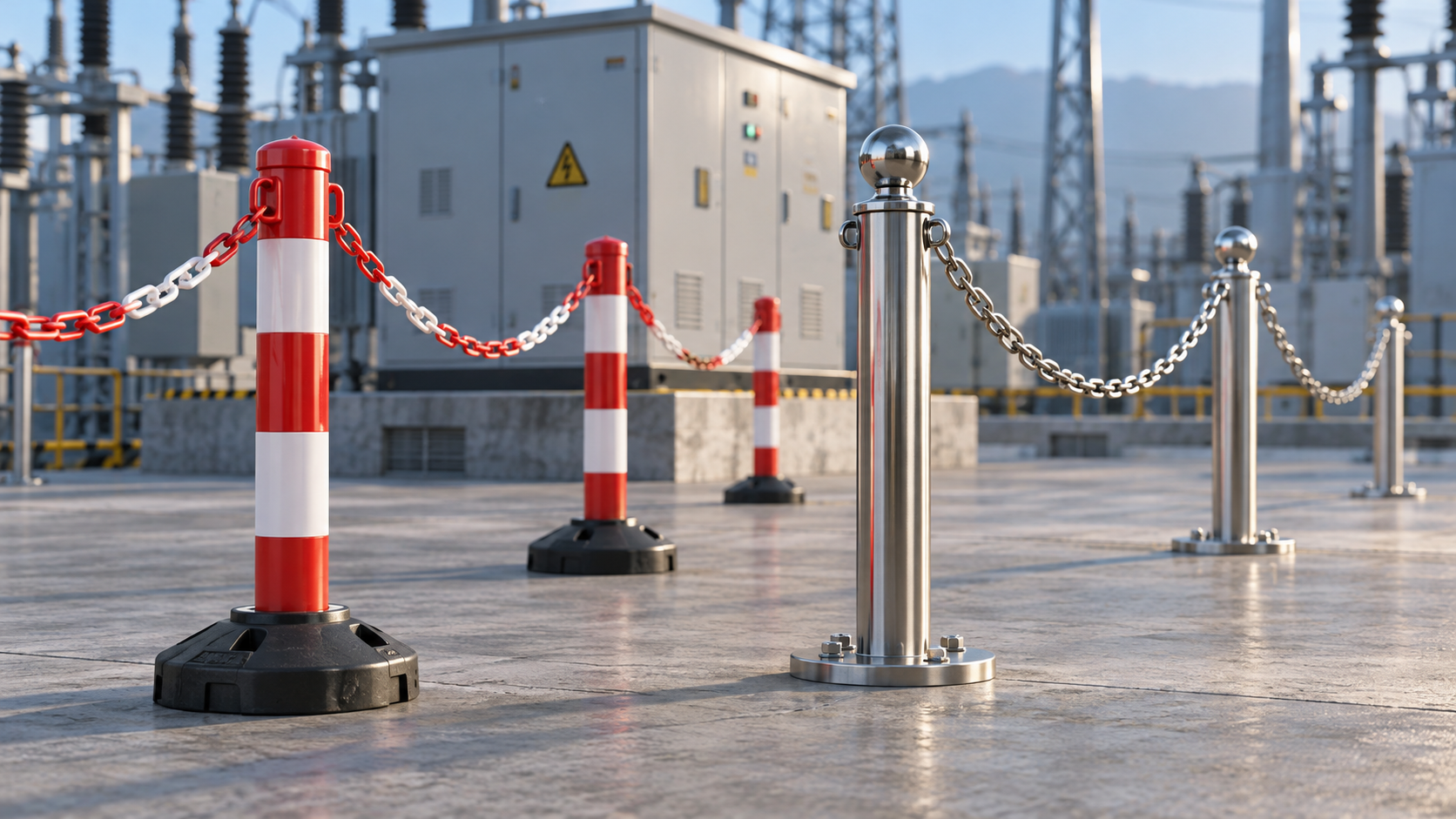
Plastic vs. Steel Barrier Stands: Which Suits Substation Maintenance?
Are plastic barrier stands better than steel ones for substation maintenance? Compare electrical considerations, stability, and durability to choose the right system for your crew.
- Nov 01, 2026
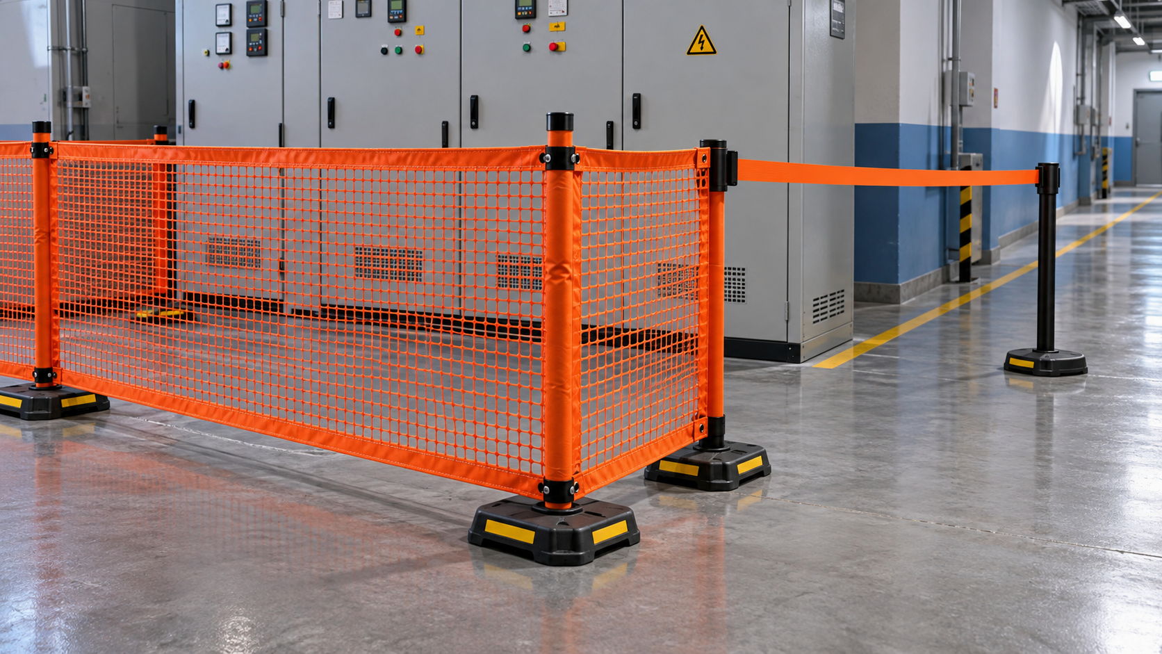
Is Mesh More Visible Than a Single Belt Around a Work Area?
Is a mesh barrier easier to see than a single belt around a work area? Compare visibility, lighting, and site conditions to choose the right boundary for electrical maintenance.
- Oct 31, 2026
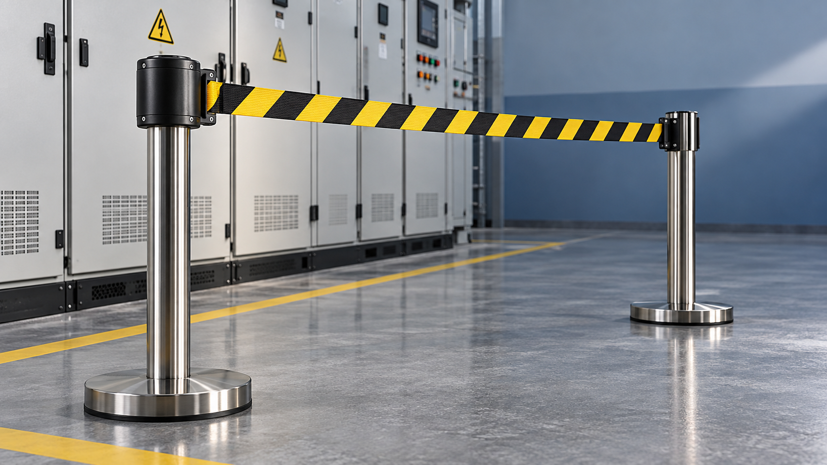
How Do You Evaluate Slow-Retracting Safety Barriers?
Evaluate slow retracting safety barriers with practical checks for controlled return, secure mounting, and durability. Discover how to choose the right barrier for electrical work zones.