
 English
 Español
 Português
 Français
 Deutsch
 русский
 한국어
 にほんご
 हिन्दी, हिंदी
 বাংলা
 Bahasa Indonesia
 Türkçe
 Việt
 dansk
 čeština
 עִבְרִית Ivrit
 Filipino/Pilipino
 български език (Bǎlgarski jazik)
 suomi
 norsk
 język polski
 ไทย
 ກະຣຸນາ
 Bahasa Melayu
 ភាសាខ្មែរ
 ဗာရမ်
 اردو
 فارسی
 Italiano
 Nederlands
 svenska
 Монгол хэл
 नेपाली
 සිංහල
 Ўзбек тили
 پښتوتۆرکجه
 Ελληνικά
 српски / srpski
 magyar
 українська
 Kiswahili
 Қазақ тілі
 Română
 Hrvatski
 Bosanski
 Kreyòl ayisyen
 አማርኛ
 Hausa
 Yorùbá
 Igbo
‹
›
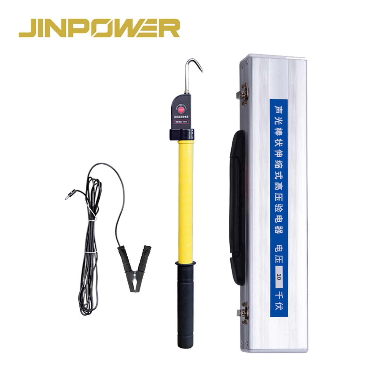
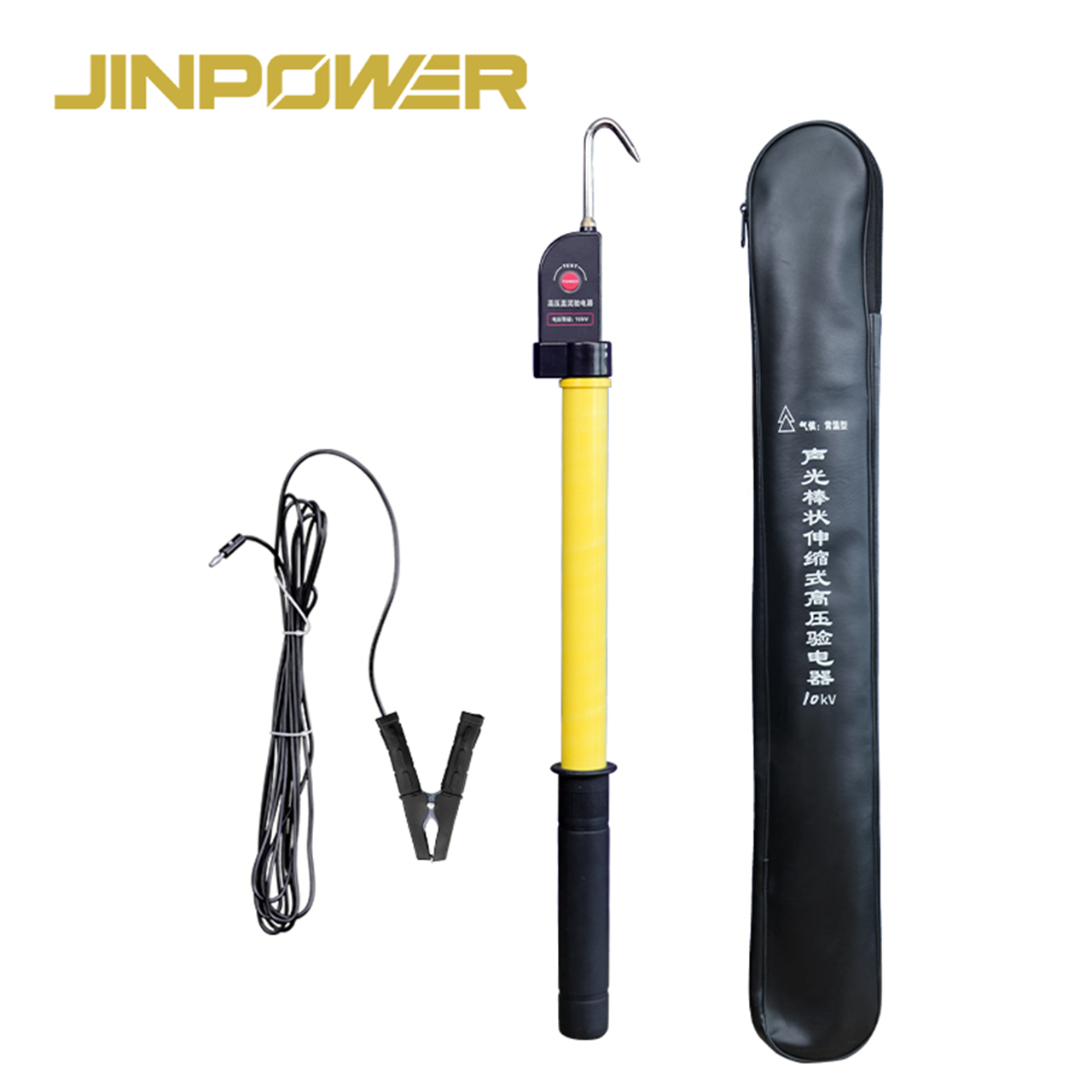
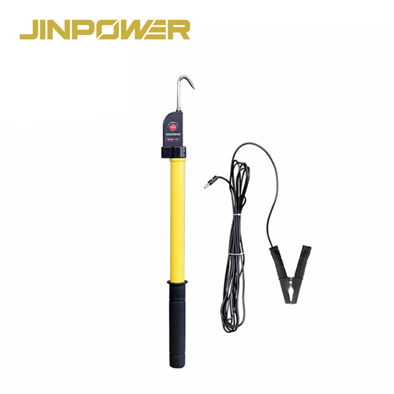
DC Voltage Electroscope with Insulated Operating Rod
JINPOWER supplies DC Voltage Electroscopes for checking the presence of Direct Current (DC) voltage in railway, utility, renewable-energy, BESS and industrial electrical systems.
The current product series includes 0.75 kV, 1.5 kV, 4.8 kV and 10 kV DC configurations. The detector combines a DC detection head, an insulated fiberglass / FRP operating rod, audible and visual indication, and a Manual Self-Test function.
For professional buyers, the key questions are simple: What is the actual DC system voltage? Which detector configuration matches that voltage? What is the required rod length? What detection method does the project require? And what test or technical documents need to be supplied?
All Products
Stay Connected
If you have any questions, please contact us and we will contact you as soon as possible.
Prduct Introdution
Product Highlights
- Designed for DC voltage presence detection
- 0.75 kV / 1.5 kV / 4.8 kV / 10 kV DC configurations
- Insulated fiberglass / FRP operating rod
- Single-section fixed rod construction in the current product configuration
- Audible buzzer + visual indicator
- Manual Self-Test function
- Rubberized anti-slip handle
- Suitable for railway, BESS, PV, substation and industrial DC applications
- Protective carry package available according to product configuration
Quick Technical Specification
Available DC Voltage Configurations
The 0.75 kV, 1.5 kV, 4.8 kV and 10 kV ratings should be understood as different product configurations. They do not mean that one detector automatically covers every DC voltage from 0.75 kV to 10 kV.
Before ordering, confirm the rated detection range of the exact model rather than selecting a detector only because its product name includes a higher voltage number.
Quick Selection Guide
What Is a DC Voltage Electroscope?
A DC Voltage Electroscope is a safety testing device used to help determine whether recognizable Direct Current voltage is present in electrical equipment, conductors or DC circuits.
Its main purpose is voltage presence verification rather than precise numerical voltage measurement.
The insulated operating rod allows the detector head to be positioned at the required test location while the operator remains at the working position defined by the site procedure.
A “No Alarm” or “No Voltage” indication should not be treated by itself as proof that equipment is safe to touch or that electrical work can immediately begin.
Why Use an Insulated Operating Rod?
The insulated rod is not there simply to make the detector longer. Its role is to position the detector head while providing physical separation between the operator and the target electrical equipment.
For the current product configuration, the rod shown is a straight fixed-length structure rather than a multi-section telescopic pole.
When choosing a model, confirm:
- Required operating reach
- Location of the detection point
- Available working space
- System voltage
- Site working-distance requirements
- Rod length specified by the project
The exact rod length should be confirmed from the model specification rather than assumed from the product image.
DC Voltage Detector vs AC Voltage Detector
DC and AC electrical systems behave differently, so two products called “Voltage Detectors” should not automatically be treated as interchangeable.
When requesting a quotation, always state whether the target electrical system is DC or AC rather than providing only a voltage number.
DC Voltage Electroscope vs Multimeter
If your job requires an exact value such as 824 V or 1,490 V, use an appropriately rated measuring instrument rather than treating the DC Voltage Electroscope as a precision voltmeter.
Main Structure of the JINPOWER DC Voltage Electroscope
Detection Head
The Detection Head is the main component responsible for detecting the presence of DC voltage.
The exact detection principle and connection method should be confirmed from the Technical Specification of the selected model.
Do not classify the detector as “contact” or “non-contact” only from its appearance unless the product documentation clearly confirms the detection method.
Audible and Visual Indication
When the selected detector responds to DC voltage within its specified operating conditions, audible and visual indicators help the operator recognize detector status.
Dual indication can be useful in noisy work areas or locations where lighting conditions change.
The alarm remains only one part of the full voltage-verification process.
Manual Self-Test Function
The Manual Self-Test function is used to check whether the detector's basic alarm and indicator functions respond before formal use.
A successful Self-Test confirms basic internal response. It does not automatically prove that the detector will correctly perform in every electrical environment.
The detector should still be used according to the product instructions and site voltage-verification procedure.
Single-Section FRP Insulating Rod
The current product configuration uses a straight fiberglass / FRP insulating rod between the detector head and operator grip.
Because there are no telescopic joints in this configuration, routine inspection focuses mainly on the condition of the full rod surface rather than telescopic locks or sliding sections.
Rubberized Anti-Slip Handle
The lower grip area provides a more stable hand position during operation.
The handle is a handling feature and does not replace the electrical PPE required by the task.
How to Select the Right DC Voltage Configuration
1. Confirm the Nominal DC Voltage
Start with the actual DC operating voltage of the equipment or system.
Railway traction, BESS, PV and industrial DC systems may use very different voltage levels.
2. Confirm the Actual Detection Range
Instead of requesting a general “high-voltage DC detector,” provide the minimum and maximum DC voltage expected at the test location.
3. Confirm the Detection Method
If the tender, utility specification or site procedure requires a particular detection principle or connection arrangement, state that requirement during the RFQ stage.
4. Confirm the Detection Point
Busbars, conductors, rail traction equipment, DC cabinets and other equipment may require different detector heads, rod lengths or operating methods.
5. Confirm the Required Rod Length
Rod length should be based on the actual equipment location, operator position and site working-distance requirement.
Do not assume a particular rod length until the selected model specification has been confirmed.
Voltage Detection Does Not Mean the Equipment Is Safe to Touch
This is one of the most important limits to understand when using any voltage detector.
A “No Alarm” or “No Voltage” indication by itself does not replace:
- Isolation Procedure
- Lockout / Tagout where applicable
- Required Voltage Verification Procedure
- Temporary Grounding where required
- Site Safety Authorization
- Required Electrical PPE
The detector, its rated range, detection method and site procedure all need to match before the result is used as part of a safety decision.
Voltage Detection Before Temporary Grounding
Where an approved maintenance procedure requires temporary grounding, voltage verification normally takes place before the grounding equipment is installed.
A simplified workflow can be understood as:
Isolate → Verify Voltage Status → Confirm According to Procedure → Apply Grounding → Work
The DC Voltage Electroscope supports the voltage-verification step. It does not replace isolation or grounding equipment.
For related products, see JINPOWER Grounding Equipment.
Main Applications
Railway and Metro DC Traction Systems
Railway, metro and tram traction systems are common applications for DC voltage detection.
For systems around 750 V DC or 1.5 kV DC, the correct detector should be selected according to the actual traction voltage, detection location and maintenance procedure.
Substation and Converter Station DC Systems
Substations and converter stations may contain DC buses, control power, auxiliary circuits and other DC systems that require voltage presence verification.
Do not confuse the voltage of the overall substation or HVDC facility with the rating of the local DC circuit being tested.
A detector from this series should only be used where the selected model's rated range matches the actual target circuit.
Battery Energy Storage Systems (BESS)
BESS installations can include high-voltage DC battery strings, DC buses and associated electrical equipment.
A DC Voltage Electroscope can be considered where the actual voltage, detector range and detection method match the BESS manufacturer's maintenance procedure and site safety program.
Solar PV DC Systems
PV strings, combiner systems and DC buses may operate at significant DC voltage.
A detector labeled 1.5 kV should not automatically be assumed suitable for every point in a 1.5 kV PV installation. The actual detection range, detection point and operating method still need to be confirmed.
Industrial DC Equipment
Industrial DC distribution systems, drives, motors, automation equipment and other DC circuits may also require voltage presence verification during maintenance.
For compact cabinets and equipment rooms, rod length and available working space should be confirmed before selecting the detector.
Training and Testing Facilities
Electrical training centers and testing facilities may also use DC Voltage Electroscopes when the training voltage, equipment configuration and procedure match the selected detector.
What Should Be Checked Before Use?
Inspect the Detection Head
- Housing cracks or impact damage
- Damage around the detection area
- Condition of visible leads or connection parts where fitted
- Condition of the indicator
- Readable model and voltage-range marking
Perform the Manual Self-Test
Use the Self-Test function according to the product instructions to check the basic response of the alarm and indicator system.
The Self-Test does not replace the complete detector-verification procedure required by the site.
Inspect the Insulating Rod
- Cracks
- Deep scratches
- Exposed fibers
- Surface contamination
- Moisture
- Impact damage
- Other visible deterioration
Verify the Rated Range
Before testing, confirm that the exact detector configuration being used matches the actual DC voltage of the target circuit.
Storage and Maintenance
- Keep the detector and insulating rod clean and dry
- Avoid prolonged exposure to oil, chemicals and conductive contamination
- Protect the detection head from impact
- Avoid deep scratches or damage to the FRP rod
- Protect leads and connection parts from pulling or crushing where fitted
- Use the protective package during transport and storage
- Check battery and electronic functions according to the product instructions
- Maintain inspection and test records where required by the project safety program
When Should the Detector Be Removed from Service?
Stop using the detector and arrange inspection if its electronic function, structural condition or insulating integrity is uncertain.
- Self-Test does not respond normally
- Audible or visual indication is abnormal
- Detection head is damaged
- Housing is cracked
- Rated voltage label is unreadable
- FRP rod is cracked or severely scratched
- Fiberglass is exposed
- Lead or connection component is visibly damaged where fitted
- The product has suffered serious impact or water ingress
- The detector fails a project-required functional or inspection test
Standards and Test Documentation
Voltage-detector standards should not be applied only because two products have a similar name or appearance.
Different DC detector designs, voltage ranges and detection principles may require different technical evaluation.
For project approval, buyers should confirm:
- The product is intended for DC systems
- Rated DC detection range
- Detection method
- Alarm / indicator function
- Self-Test requirement
- Insulating rod requirement
- Destination-market requirement
- Utility or tender specification
- Required test and inspection documents
If a tender specifies a particular standard or test method, include it before quotation and sample approval rather than adding it after production.
DC Voltage Detector Buyer Acceptance Checklist
JINPOWER Pre-Shipment Checks
For utility, distributor and EPC orders, the main goal before shipment is to confirm that the supplied detector matches the approved purchase specification.
- DC voltage configuration
- Detector head condition
- Audible and visual indication
- Manual Self-Test response
- Insulating rod condition
- Rod length
- Handle condition
- Lead or connection components where supplied
- Product marking
- Packaging
- Required technical documentation
If your project requires third-party inspection, specific functional testing or additional acceptance documents, include those requirements before the order is confirmed.
OEM and Project Configuration
JINPOWER supports project and bulk purchasing for utilities, railway contractors, renewable-energy projects, electrical distributors and industrial buyers.
Depending on the selected product configuration, project discussions may include:
- DC voltage configuration
- Insulating rod length
- Product label
- Serial identification
- Logo / branding
- Carry packaging
- Technical documentation
How Does the DC Detector Fit Into an Electrical Safety System?
Voltage detection is one part of an electrical safety workflow. Depending on the job, the project may also require insulated operating tools, temporary grounding equipment and electrical PPE.
Related JINPOWER products includeVoltage Detectors,AC High Voltage Detectors,Grounding EquipmentandHot Sticks and Insulated Operating Tools.
DC Voltage Electroscopes and AC High Voltage Detectors should not be treated as interchangeable simply because they have similar names.
Why Choose JINPOWER DC Voltage Electroscopes?
Focused on Electrical Safety Equipment
JINPOWER supplies voltage detectors, insulated operating tools, grounding equipment and electrical PPE for utility and industrial applications.
Multiple DC Voltage Configurations
The current 0.75 kV, 1.5 kV, 4.8 kV and 10 kV configurations give buyers clearer options for different DC applications instead of using one vague “high-voltage detector” description.
Project-Based Selection
We recommend selecting the detector based on actual DC voltage, detection method, required rod length and equipment layout instead of simply choosing the highest voltage model.
B2B Project Procurement Support
For utility tenders, EPC projects and distributor orders, voltage configuration, rod length, labeling, packaging and technical documentation can be confirmed before production.
What Should You Include in Your RFQ?
Frequently Asked Questions
What is a DC Voltage Electroscope used for?
It is used to help determine whether recognizable voltage is present in a DC electrical system as part of the voltage-verification process before maintenance or other approved electrical work.
Is this DC Voltage Electroscope telescopic?
The current product configuration shown on this page uses a fixed single-section insulating rod rather than a multi-section telescopic pole. Exact rod length should be confirmed for the selected model.
Can it measure the exact DC voltage?
No. It is mainly intended for voltage presence detection. Use a properly rated measuring instrument when an exact numerical voltage value is required.
Does one detector cover every voltage from 0.75 kV to 10 kV?
Do not assume so. The 0.75 kV, 1.5 kV, 4.8 kV and 10 kV values represent different detector configurations. Confirm the rating of the exact model being supplied.
Is this a contact or non-contact DC Voltage Detector?
The detection method should be confirmed from the Technical Specification of the selected model. It should not be assumed only from the external appearance of the detector.
Can a DC Voltage Detector be used on AC systems?
Not by default. DC and AC detectors should be selected according to the target electrical system, detector design and rated range.
What does the Self-Test function do?
It checks whether the detector's basic alarm and indicator functions respond. It does not complete the full on-site voltage-verification procedure.
Does “No Alarm” mean the equipment is safe to touch?
No. A No Alarm result is only one part of the safety process. Isolation, voltage verification, grounding where required, authorization and PPE procedures still need to be completed.
How should I choose the insulating rod length?
Choose rod length according to the actual detection point, operator position, required working distance and equipment layout. Confirm the exact model dimension before ordering.
Can it be used for railway DC traction?
It can be considered where the actual traction voltage, detection location, detector rating and work procedure match the selected model.
Can it be used for BESS and Solar PV?
Potentially, but suitability should be confirmed against the actual DC voltage, detection point, detector method and selected product rating.
Can JINPOWER provide project-specific configurations?
Voltage configuration, insulating rod length, labeling, branding, packaging and technical documentation can be discussed according to the confirmed project requirement.
Request DC Voltage Electroscope Details and Pricing
If you are sourcing a DC Voltage Electroscope for railway traction, BESS, Solar PV, substations, industrial DC systems or another electrical project, send JINPOWER the actual system information rather than only asking for a “DC tester.”
Please provide the nominal DC voltage, required detector configuration, detection point, detection method if specified, required rod length, applicable standard, quantity and documentation requirements.
JINPOWER can then confirm the detector configuration and insulated operating rod requirements before quotation and project approval.
Inquiry