 English
 Español
 Português
 Français
 Deutsch
 русский
 한국어
한국어 にほんご
にほんご हिन्दी, हिंदी
 বাংলা
বাংলা Bahasa Indonesia
 Türkçe
 Việt
Việt dansk
dansk čeština
 עִבְרִית Ivrit
 Filipino/Pilipino
 български език (Bǎlgarski jazik)
 suomi
suomi norsk
norsk język polski
 ไทย
ไทย ກະຣຸນາ
 Bahasa Melayu
 ភាសាខ្មែរ
 ဗာရမ်
ဗာရမ် اردو
اردو فارسی
فارسی Italiano
 Nederlands
 svenska
 Монгол хэл
 नेपाली
 සිංහල
සිංහල Ўзбек тили
 پښتوتۆرکجه
 Ελληνικά
 српски / srpski
 magyar
 українська
 Kiswahili
 Қазақ тілі
 Română
 Hrvatski
 Bosanski
 Kreyòl ayisyen
 አማርኛ
አማርኛ Hausa
Hausa Yorùbá
 Igbo
IgboWhat grounding equipment is required for substation maintenance tasks
Substation maintenance rarely feels complicated at the moment the work permit is issued. The trouble usually starts later, when a team is standing in front of isolated equipment and someone asks a practical question: do we have the right grounding equipment for this task, or only the pieces we happened to bring? That question matters more than many planning documents admit. A missing clamp, the wrong cable size, or an unverified connection point can stop the job, delay switching steps, and create unnecessary exposure for the crew.
Many maintenance problems in substations are not caused by the main repair task itself. They come from the gap between isolation on paper and protection in the field. Even after de-energization, workers still need protection against induced voltage, backfeed, stored energy, or accidental re-energization. That is why grounding equipment is not a single item. It is a coordinated set of components selected for the actual configuration of the bay, bus, feeder, transformer, or cable section being maintained.
Where planning often goes wrong
A common mistake is to treat temporary grounding as a generic accessory rather than part of the work method. In reality, the grounding arrangement depends on conductor spacing, available attachment points, fault current expectations, approach distances, and whether the work is being done on busbars, disconnectors, cable terminations, or apparatus bushings.
Another frequent issue is assuming that one standard set can cover every substation task. It usually cannot. A compact indoor switchgear room, an outdoor AIS yard, and a transformer maintenance area all present different physical constraints. The grounding equipment needed for each location may vary in cable length, clamp style, phase spacing, ferrule construction, and the type of earthing point available.
If you are reviewing a maintenance package and trying to prevent last-minute field changes, it helps to think in terms of function rather than inventory count. The goal is not simply to “have temporary grounds.” The goal is to create a visible, low-impedance path to earth at the right location, with components matched to the system and installed in a safe sequence.
The core equipment normally required
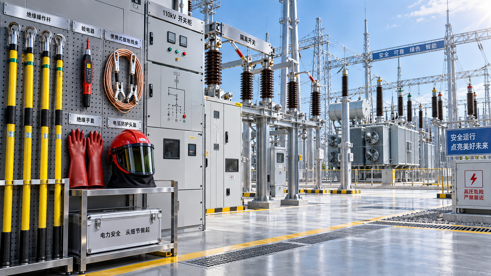
For most substation maintenance work, the essential grounding equipment starts with the temporary grounding set itself. That set typically includes grounding cables, phase leads where required, grounding clamps, and a connection to an approved earth point. Depending on the layout, it may be configured as a three-phase set, a single-point grounding set, or a cluster-bar arrangement for multiple phase connections.
The cable is not a minor detail. It must be selected for expected fault duty, mechanical handling, flexibility, and the practical routing space at the work location. A cable that is too stiff may be difficult to apply safely in confined areas. A cable that is too short can force awkward positioning. A cable chosen without considering possible fault current may not match the protection requirement of the system.
Clamps deserve equal attention. The grounding clamp has to match the geometry and material of the conductor or grounding point. Flat busbars, round conductors, grounding studs, and structural earth points often require different clamp designs. Using an ill-fitting clamp is one of the easiest ways to undermine an otherwise good grounding plan. Secure contact pressure and stable attachment matter because a temporary ground must remain reliable throughout the full maintenance period, not just during installation.
Many teams also require an operating pole or insulated installation tool to apply and remove grounds from a safe distance. Even where the equipment is already isolated, the application process must respect approach boundaries and the possibility of residual or induced voltage. In practice, the grounding set and the application tool should be planned together, not as separate purchases.
Items that are often forgotten until the day of work
The most overlooked grounding equipment is often not the main cable assembly but the supporting items needed to verify and use it properly. Before grounds are applied, crews usually need an approved voltage detector suited to the system voltage and site procedure. Temporary grounding should never become a substitute for proper absence-of-voltage verification.
Another commonly missed item is the grounding point adapter. Some substations have convenient and obvious earth points. Others do not. In older yards especially, the approved connection location may be physically awkward or may need a dedicated fitting to accept the selected clamp. If this is not reviewed during planning, the crew may arrive with a perfectly good grounding set that cannot be attached correctly.
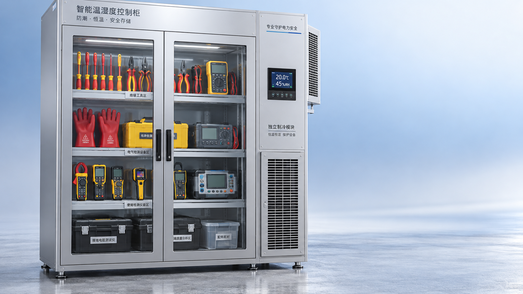
Storage and transport also affect field readiness more than many people expect. Grounding cables dragged loosely with other hardware can suffer damage to insulation covers, ferrules, or clamp surfaces. A damaged set might still look usable at first glance, which is exactly why pre-job inspection matters. Keeping sets organized by voltage class, application type, and cable size reduces confusion and speeds up work preparation.
Choosing the right set for the actual maintenance task
When selecting grounding equipment, it helps to start with the task location rather than the catalog category. Ask first where the crew will attach the ground, how many phases need to be grounded, and whether the working zone is between visible grounding points or only on one side of the isolation. This quickly narrows the options.
For bus maintenance, crews often need sets designed for wider phase spacing and busbar-compatible clamps. For cable termination work, shorter leads and compact clamps may be more suitable, especially where cabinet space is limited. Transformer-related maintenance may involve grounding on both the high-voltage and low-voltage side depending on the isolation procedure, so the set configuration must align with the switching plan.
There is also an important difference between grounding for induced voltage control and grounding for protective short-circuit duty. In some cases, the main concern is draining residual or induced charge. In others, the temporary grounding assembly must be capable of carrying substantial fault current until protective devices operate. That distinction should drive selection, because the same visual appearance does not mean the same performance level.
Where work is performed near equipment that may still be energized, personal insulating protection also enters the picture. For some maintenance activities, crews may use Insulating rubber gloves as part of the protective method. These gloves are used in live-line work, substation maintenance, electrical installation and repair, operation of electrical equipment, and high-voltage safety protection. Available voltage classes such as Class 00, 0, 1, 2, 3, and 4, and standards including IEC 60903 and ASTM D120, are relevant when matching hand protection to the task. They do not replace temporary grounds, but they can be part of the overall protection approach when procedures call for insulation against accidental contact or nearby energized parts.
Sequence matters as much as the hardware
Even well-selected grounding equipment can be misused if the application sequence is poorly controlled. In general field practice, the earth end is connected first and removed last. This reduces the chance of a worker handling an ungrounded lead while establishing the connection. The phase-side attachment then follows according to site procedure and equipment layout.
Before that sequence starts, the work area needs to be confirmed as correctly isolated, identified, and tested for absence of voltage using the approved method. Once the grounding set is installed, the crew should be able to see that the protection is in place and understand exactly which conductors are bonded to earth. If visibility is poor or the installation path is complicated, the risk of misunderstanding increases.
This is one reason managers often prefer grounding equipment designed for straightforward handling in the actual space available. A technically adequate set that is hard to install cleanly in a crowded panel or elevated yard location invites workarounds. Good planning reduces the temptation to improvise.
How to review suitability before approving purchase or deployment
If you are responsible for deciding whether a grounding set is suitable, avoid making the decision on cable cross-section alone. A better review includes at least these practical questions: what is the system voltage, what fault level or duty must be considered, what type of conductor will the clamp contact, what are the required lead lengths, how will the set be applied, and how will it be inspected and stored between jobs?
It also helps to compare the planned set with the substation’s actual physical constraints. Are there narrow compartments? High bus positions? Outdoor exposure to moisture or contamination? Repeated handling in rough transport conditions? Equipment that looks acceptable in a specification sheet may prove frustrating if the clamp profile is awkward or the cable routing is unrealistic.
For organizations handling mixed assets, standardization can help, but only up to a point. It is reasonable to reduce unnecessary variation in connectors or storage methods. It is less reasonable to force one temporary grounding arrangement onto every substation configuration. A smaller range of well-matched sets usually works better than a single “universal” option.
Signs that your current approach needs adjustment
Sometimes the clearest warning sign is operational rather than technical. If crews repeatedly ask for extra adapters, borrow parts from other teams, or spend too much time deciding where to connect grounds, the issue may be inadequate planning rather than worker hesitation. The same is true when the grounding set is routinely placed on the work order but not specifically matched to the equipment involved.
Another sign is over-reliance on memory. In substations with mixed generations of equipment, attachment points and clearances can differ significantly from bay to bay. If successful grounding depends mostly on which experienced technician happens to be present that day, the process is not robust enough. The equipment selection and application method should be clear enough that the team can follow it consistently.
Inspection findings also deserve attention. Wear at clamp contact surfaces, looseness at ferrules, cracked insulation covers, corrosion, or unclear identification markings should not be dismissed as minor shop issues. Grounding equipment is often handled in tough environments, so degradation is normal over time. What matters is whether there is a disciplined process for checking serviceability before deployment.
A more reliable way to define requirements
Instead of asking only “what grounding equipment is required for substation maintenance tasks,” it is more useful to ask “what grounding arrangement is required for this specific maintenance task, in this specific substation section, under this switching condition?” That shift in wording tends to improve decisions immediately.
From there, the required equipment usually becomes easier to define: a temporary grounding set with appropriate cable rating and length, clamps matched to conductor and earth point geometry, insulated application tools if needed, approved voltage detection equipment, any necessary adapters, and supporting protective items consistent with the work method. In some tasks, that protective package may also include hand insulation such as Insulating rubber gloves, provided the selection aligns with the voltage class and procedure.
When grounding equipment is chosen this way, the job is less likely to stall at the worksite. More importantly, the protection method is easier for the whole team to understand and verify. That is usually the real goal in substation maintenance: not collecting more hardware, but making sure every isolation becomes a protection system that works clearly, visibly, and as intended in the field.
Recommend
 Oct 25, 2026
Homemade Bird Repellent Spray: Recipe Limits and Outdoor Surface Risks
Searching for how to make homemade bird repellent spray? Discover recipe limits, outdoor surface risks, electrical safety tips, and safer deterrents before you spray.
- Oct 25, 2026
Natural Bird Deterrents for Rooftops: Choosing Nonchemical Options
Learn how to repel birds naturally with humane rooftop barriers and smarter maintenance. Compare nonchemical options to protect electrical equipment and keep roof access clear.
- Oct 24, 2026
Home Remedies for Repelling Birds: What to Try on Patios and Railings
Learn how to repel birds with home remedies for cleaner patios and railings. Discover humane DIY options, avoid harmful sprays, and keep deterrents clear of electrical equipment.