 English
 Español
 Português
 Français
 Deutsch
 русский
 한국어
 にほんご
 हिन्दी, हिंदी
 বাংলা
 Bahasa Indonesia
 Türkçe
 Việt
 dansk
 čeština
 עִבְרִית Ivrit
 Filipino/Pilipino
 български език (Bǎlgarski jazik)
 suomi
 norsk
 język polski
 ไทย
 ກະຣຸນາ
 Bahasa Melayu
 ភាសាខ្មែរ
 ဗာရမ်
 اردو
 فارسی
 Italiano
 Nederlands
 svenska
 Монгол хэл
 नेपाली
 සිංහල
 Ўзбек тили
 پښتوتۆرکجه
 Ελληνικά
 српски / srpski
 magyar
 українська
 Kiswahili
 Қазақ тілі
 Română
 Hrvatski
 Bosanski
 Kreyòl ayisyen
 አማርኛ
 Hausa
 Yorùbá
 Igbo
Are Magnetic Barrier Mounts Suitable for Switchgear Enclosures?
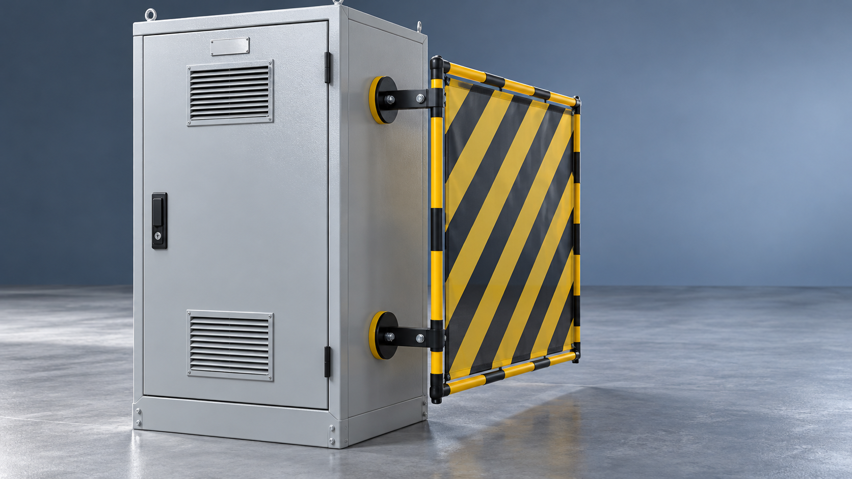
Magnetic barrier mounts are suitable for some electrical switchgear enclosures, particularly for temporary visual barriers attached to sound, flat steel surfaces. Suitability requires a compatible enclosure material, sufficient holding strength in the actual load direction, and a position that preserves electrical clearances and equipment operation. A magnet’s advertised pull force alone cannot establish whether the arrangement is acceptable.
The intended barrier function sets the limit. A temporary warning screen outside a closed cabinet presents different demands from an internal barrier intended to prevent contact with live parts. A magnetic mount provides attachment; it does not establish electrical insulation, arc protection, or an approved replacement for an enclosure component. Where the barrier performs a protective function, the complete assembly and its installation need supporting technical documentation.
The barrier’s purpose determines whether magnets are an option
An external visual barrier can mark an access restriction or separate a maintenance area without becoming part of the switchgear’s electrical protection system. Magnetic attachment is a practical option when the mounting surface and expected loads are suitable. The barrier must still remain positioned under foreseeable disturbances, including nearby movement, ventilation airflow, and accidental contact.
A barrier installed inside a compartment raises different questions. Its mounting hardware occupies space near conductors, insulation, shutters, and moving mechanisms. A detached magnet or steel bracket could become a conductive loose object. Even when the barrier sheet has documented dielectric properties, those properties do not automatically extend to the mounting arrangement.
Replacement covers, internal partitions, and components associated with arc containment require particular care. Their attachment contributes to equipment behavior under conditions far beyond normal handling. Substituting magnets for specified fasteners changes that arrangement and requires explicit equipment-manufacturer acceptance. Convenient removal is not sufficient justification.
Steel compatibility is only the first material question
Painted carbon-steel panels are plausible mounting surfaces, but their thickness, shape, and finish affect the connection. Magnetic holding-force ratings are established under specified test conditions. A thin cabinet door, a curved panel, or a thick coating creates a different magnetic circuit from a flat test plate. Strong attraction during placement does not quantify the margin available during service.
Aluminum and nonmetallic enclosures do not provide direct magnetic attachment. Stainless steel needs closer identification: some grades are strongly magnetic, while others provide weak or negligible attraction. A simple attraction test indicates whether a response exists, but it cannot establish usable load capacity.
Adding a steel backing plate changes the design. The plate itself needs secure attachment, and its location must preserve the enclosure’s protective functions. An adhesive-backed steel plate transfers the mounting problem to the adhesive, coating, and substrate beneath it. Its performance is no longer determined by the magnet alone.
Surface condition also matters. Raised labels, seams, rust scale, and uneven paint prevent full seating. Oil or condensation reduces resistance to sliding. A protective rubber covering can improve friction and limit scratches, while the additional separation from the steel affects magnetic attraction. The complete mount must therefore be assessed with its intended contact layer fitted.
Pull force does not describe the installed load
A published pull-force value commonly describes separation perpendicular to a specified steel surface. A mount supporting a barrier on a vertical cabinet wall often carries much of its load parallel to that surface. Resistance to downward sliding then depends on contact friction as well as magnetic attraction.
Barrier geometry introduces another difference. A bracket that projects away from the cabinet creates leverage. A pull on the screen’s outer edge can peel one side of the magnet away from the steel, producing release under a load well below the quoted direct pull force. A light, wide barrier exposed to airflow can be more demanding than a heavier compact panel positioned close to the mounting surface.
Several magnets do not necessarily share the load equally. Small differences in alignment, panel flatness, or bracket stiffness can leave one mount carrying most of the force. Once it moves, adjacent mounts receive a sudden increase in load. Adding individual pull ratings together gives an unreliable estimate of assembly capacity.
Useful supporting information includes the rated load direction, reference steel thickness, surface finish, temperature range, and mounting geometry. Verification should represent the intended installation, including the barrier’s mass and foreseeable disturbances. Any physical evaluation around switchgear belongs within an approved work arrangement, with electrical hazards controlled before mounting or testing begins.
Comparing magnetic mounts with other attachment methods
The appropriate comparison is between complete attachment arrangements performing the same barrier function. Each method places different demands on the enclosure and offers a different balance between removability and positive retention.
Magnetic mounting has a clear advantage when repeated removal is necessary and the enclosure cannot accept new holes. Positive mechanical attachment becomes more attractive where displacement would expose hazardous parts or where the barrier must remain installed for extended periods. Existing manufacturer-approved attachment points deserve consideration before any enclosure modification.
Placement can rule out an otherwise strong mount
A mechanically secure mount can still occupy an unacceptable location. Conductive magnets, cups, brackets, and fasteners must preserve the electrical clearances applicable to the equipment. The assessment needs to account for the full assembly, including fastener ends and any movement permitted by the bracket. An insulating sheet does not make nearby conductive hardware electrically irrelevant.
Clearance also has a mechanical meaning. Doors must close and latch correctly; shutters, racking mechanisms, handles, and interlocks need their full travel. Attaching a barrier to a door introduces movement whenever that door opens. A connection that appears stable with the cabinet closed may rotate, slide, or collide with adjacent equipment during operation.
Ventilation openings and pressure-relief features must remain unobstructed. Covering a grille changes airflow, while a barrier positioned across an intended exhaust path can interfere with the equipment’s designed response. These locations require the equipment documentation to guide placement.
Magnetic fields can also matter near magnetically sensitive devices, including some sensors and switching components. Compatibility depends on the device and separation distance; there is no universal spacing rule for every enclosure. Where documentation leaves the interaction unresolved, a different attachment location or method avoids relying on an unsupported assumption.
Repeated installation changes what needs attention
Temporary mounts often move between cabinets, so an arrangement accepted on one enclosure should not automatically be transferred to another. Similar-looking panels can differ in material, thickness, coating, and stiffness. Even within one lineup, a door and a fixed frame member can provide substantially different attachment conditions.
Magnetic faces also collect ferrous debris. Trapped particles prevent full seating and scratch coatings during repositioning. Damaged coating creates a maintenance issue, particularly where moisture is present. Mount inspection therefore includes the contact face and protective covering, as well as the bracket and fasteners.
Temperature limits apply to the entire assembly. The magnet, protective pad, bonded components, and barrier sheet can have different service limits. Local conditions near warm panels or ventilation outlets deserve attention even when the surrounding room remains comfortable. Outdoor exposure adds moisture, corrosion, and wind loading to the assessment.
A retention tether can limit the consequences of detachment only when its anchor and route are suitable. An improvised conductive tether near live components creates another hazard, and a long tether can allow the barrier to strike equipment. Secondary restraint needs its own defined function and installation details.
Evidence that supports a defensible choice
The most useful documentation connects the mount to the actual barrier and enclosure. A magnet catalog rating leaves too many installation variables unresolved. An assembly drawing should show mount spacing, barrier dimensions, offsets, contact surfaces, and the relationship to nearby equipment features.
The barrier’s intended function should be stated just as clearly. “Temporary visual segregation” and “protection against contact with energized parts” demand different evidence. If electrical protective performance is claimed, the relevant documentation needs to address the complete protective arrangement and its conditions of use. A dielectric test on the sheet material alone does not establish retention, stability, or protection around its edges.
Acceptance criteria should describe what counts as failure during verification: sliding, rotation, partial separation, permanent deformation, or movement that reduces a required clearance. This is more useful than an informal judgment that the magnet feels strong. The assessment should also consider the result of one mount releasing, especially where the remaining assembly could swing toward hazardous parts.
Magnetic mounting is a reasonable choice when the barrier function permits it and the installed assembly has demonstrated adequate retention without interfering with the enclosure. An unresolved protective function, unsuitable substrate, or unverified load path is a reason to select an approved mechanical fixing or an independent barrier arrangement. The decision should remain tied to the specific enclosure and installation geometry; moving the same barrier elsewhere creates a new mounting condition to evaluate.
Next:No more content
Recommend
 Nov 02, 2026
Are Magnetic Barrier Mounts Suitable for Switchgear Enclosures?
Are magnetic barrier mounts suitable for electrical switchgear enclosures? Discover key checks for steel compatibility, holding strength, and placement to choose the right mounting solution.
- Nov 02, 2026
Is a Longer Retractable Barrier Belt Worth the Extra Cost?
Is a longer retractable belt worth the extra cost? Compare setup savings, stability, and retraction quality to find the best-value access barrier for your electrical equipment area.
- Nov 01, 2026
Plastic vs. Steel Barrier Stands: Which Suits Substation Maintenance?
Are plastic barrier stands better than steel ones for substation maintenance? Compare electrical considerations, stability, and durability to choose the right system for your crew.