English
 Español
 Português
 Français
 Deutsch
 русский
 한국어
 にほんご
 हिन्दी, हिंदी
 বাংলা
 Bahasa Indonesia
 Türkçe
 Việt
 dansk
 čeština
 עִבְרִית Ivrit
 Filipino/Pilipino
 български език (Bǎlgarski jazik)
 suomi
 norsk
 język polski
 ไทย
 ກະຣຸນາ
 Bahasa Melayu
 ភាសាខ្មែរ
 ဗာရမ်
 اردو
 فارسی
 Italiano
 Nederlands
 svenska
 Монгол хэл
 नेपाली
 සිංහල
 Ўзбек тили
 پښتوتۆرکجه
 Ελληνικά
 српски / srpski
 magyar
 українська
 Kiswahili
 Қазақ тілі
 Română
 Hrvatski
 Bosanski
 Kreyòl ayisyen
 አማርኛ
 Hausa
 Yorùbá
 Igbo
Barrier Tape Stands: Base Weight and Stability on Uneven Factory Floors
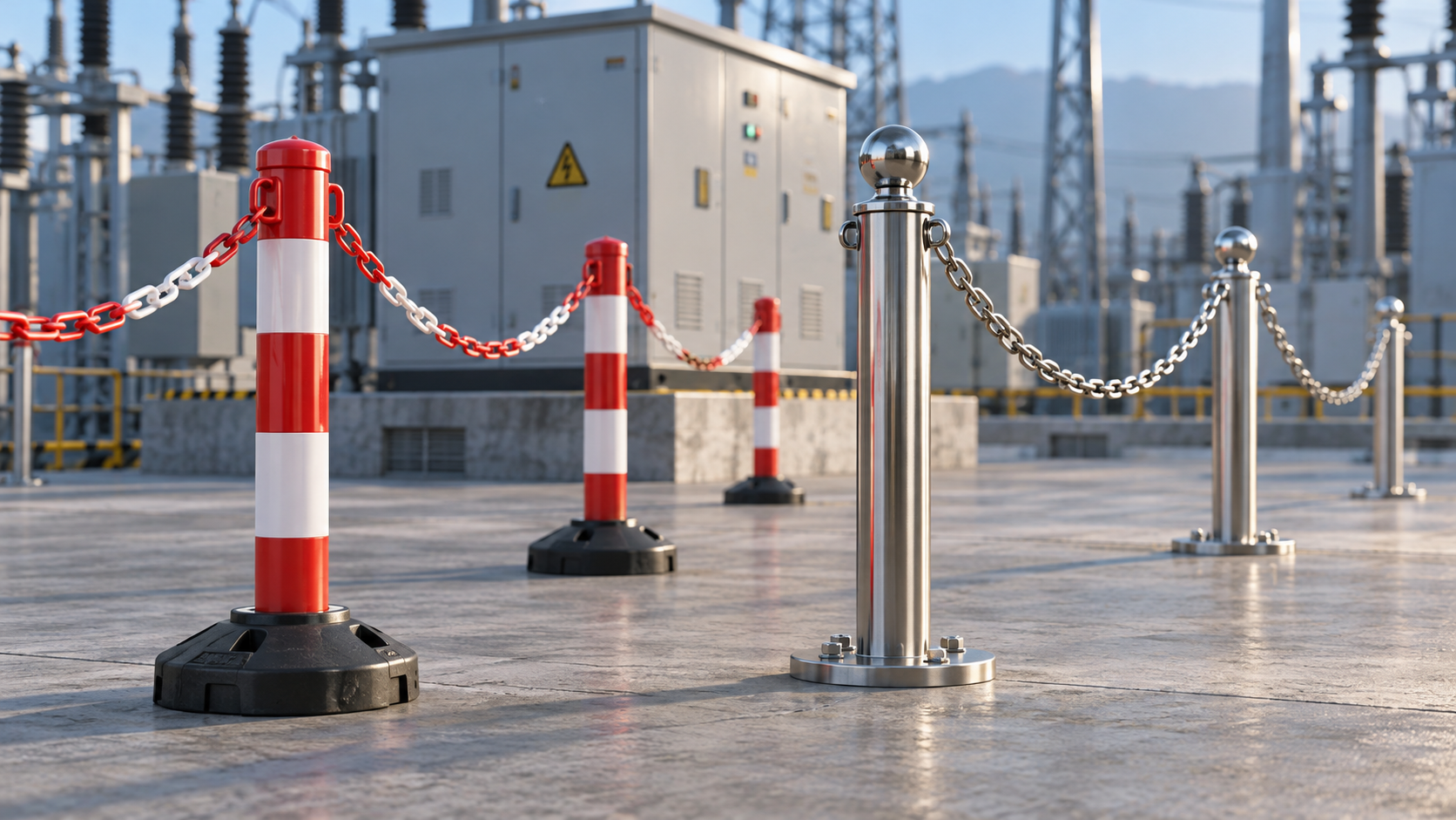
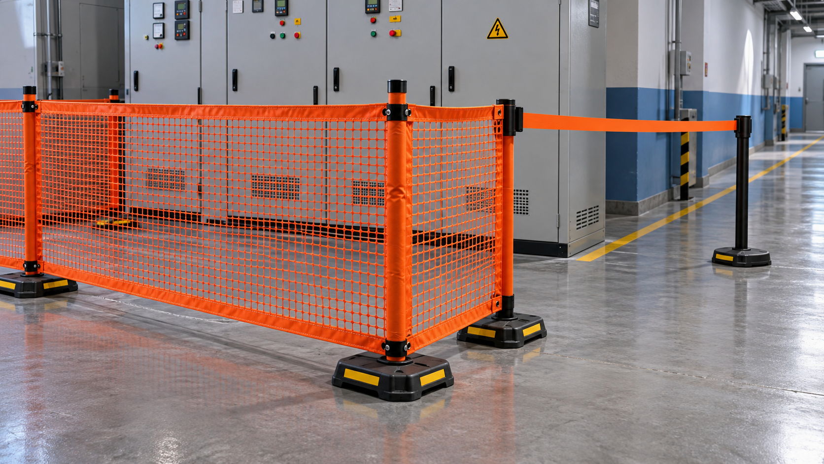
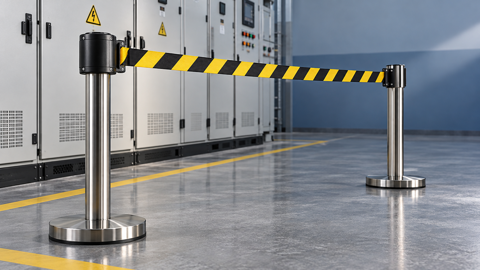
On uneven factory floors, barrier tape stands should be selected by their resistance to tipping and sliding in the actual installation—not by base weight alone. A heavy stand can still rock across a floor joint, lean on a slope, or move when tape pulls against the top of the post. Start with a stable support footprint, low-mounted ballast, and suitable floor contact, then confirm performance at the intended tape height and span.
Near electrical maintenance zones, movement can shift a marked boundary into an access aisle or leave an unintended opening. The practical choice is therefore the lightest manageable design that remains stable under the expected conditions, with an appropriate margin established through evaluation. Tape barriers provide visual access control; they are not electrical insulation, fall protection, or a means of stopping vehicles.
Separate tipping, sliding, and rocking before comparing bases
These three failure modes need different remedies. Adding ballast may improve one while leaving another unresolved.
- Tipping: The stand rotates around an edge of its effective support area. Tape tension applied high on the post creates an overturning moment.
- Sliding: The base translates across the floor without initially tipping. Floor contamination, contact material, slope, and horizontal loading affect this behavior.
- Rocking: The base alternates between contact points because the supporting surface is irregular. This changes the effective tipping edge and can introduce repeated movement as tape loads fluctuate.
A stand that rocks when gently checked before tape installation has a seating problem, not necessarily a weight problem. A stand that sits firmly but moves when the tape is attached may have inadequate friction, excessive tape tension, or insufficient overturning resistance. Record the observed motion rather than describing every failure as “unstable.”
Base weight only works through the available support geometry
For a simplified static check on a level surface, overturning moment is approximately horizontal tape force multiplied by its height above the floor. The opposing moment is approximately total stand weight multiplied by the horizontal distance from the combined center-of-gravity projection to the tipping edge.
Screening relationship: F × h < W × b, where F is the resultant horizontal pull, h is its application height, W is the stand’s total weight expressed as a force, and b is the effective resisting lever arm.
This relationship explains why two stands with the same mass can behave differently. A wider support footprint usually increases the resisting lever arm. Lower-mounted ballast keeps the center of gravity lower, improving behavior as the stand tilts or experiences disturbance. A tall post with a compact base may need substantially more ballast than a lower arrangement carrying the same horizontal load.
The equation is not an acceptance test. It omits dynamic pulls, floor slope, rocking, post flexibility, and changing contact points. Do not treat a calculation close to balance as adequate stability. Obtain supplier test conditions or use a controlled site evaluation to establish a suitable margin for the application.
Nominal diameter can overstate the useful footprint
The outer edge of a base is not always its effective support boundary. A molded base may rest on a smaller central ring. Separate feet may bridge a depression, leaving only two meaningful contacts. A wide shell can therefore provide less resistance than its dimensions suggest.
Inspect the underside and identify the load-bearing surfaces. For noncircular bases, check the weakest pulling direction: a design may resist loads well along one axis but poorly across another. At corners, the resultant tape force may act in precisely that weaker direction.
Match floor contact to the irregularity
Factory floors present different problems that should not be grouped under “uneven.” A broad slope tilts the entire stand. A local ridge can create a rocking pivot. A recessed joint may remove support beneath one foot. Oil or dust may reduce friction even where the floor appears level.
A compliant rubber contact layer may accommodate minor texture and improve grip, but it cannot reliably correct a large height difference. Friction also depends on the particular floor finish and contamination; “rubber base” is not a universal slip-resistance specification.
Adjustable feet can help establish contact where the design provides them. Their adjustment range, locking method, and bearing area matter. Unsupported modifications or loose improvised shims can shift during use and introduce trip hazards. Where a location cannot support the stand properly, moving the barrier line is generally more defensible than compensating with unsecured packing.
Tape layout can matter more than extra ballast
Evaluate the complete barrier arrangement rather than a single stand with an unloaded post. At a straight intermediate position, opposing tape pulls may partly balance. An end stand receives an unbalanced pull, while a corner stand receives the vector sum of pulls in different directions. Unequal tension or release of one tape section can change that loading immediately.
Check these positions separately. A stand that works in the middle of a straight run may be unsuitable at the end of the same run.
For retractable systems, ask for retraction force across the intended extension range. For manually attached tape, installation practice controls much of the tension. Pulling tape tight to eliminate all sag can impose unnecessary load, while excessive slack can compromise boundary visibility or allow tape into a walkway. Follow the system’s operating instructions rather than judging tension by appearance alone.
Reducing attachment height reduces overturning moment for the same horizontal force, but the barrier must remain visible and suitable for its access-control purpose. Shorter spans can reduce unsupported tape length and movement; they do not automatically reduce spring-generated tension in a retractable system. Use supplier span limits and evaluate the actual configuration.
Doorway drafts, ventilation outlets, snagging, and abrupt retraction create loads that a static pull may not represent. Where routine pedestrian or equipment contact is foreseeable, reconsider the barrier type or route. Additional base weight does not turn a tape line into a physical protective barrier.
Compare base designs by their operating trade-offs
Solid weighted bases offer a consistent ballast condition and straightforward inspection. Their limitations are handling effort and potentially poor seating across irregularities. Confirm both the complete assembly mass and whether the post can be separated safely for relocation.
Fillable bases reduce transport weight when empty, but operating stability depends on the specified fill material and fill level. Ask for filled mass, closure details, and inspection requirements. Partial filling or leakage changes the evaluated condition; an empty-base specification says little about installed stability.
Wide, low-profile bases can improve overturning resistance without relying entirely on added mass. However, the footprint may intrude into pedestrian routes, interfere with cleaning, or sit partly over a floor joint. Check usable clearance around the installed base, not just the post centerline.
Multi-foot or adjustable designs may offer placement flexibility, but contact geometry and adjustment security need inspection. Wheeled designs require particular care: confirm how the stand transfers load to the floor during use and whether the intended locking arrangement prevents movement under tape loading.
For frequent relocation, assess handling as part of selection. Carrying handles, separable components, and manageable component weights can make a stable design practical. A base that operators routinely drag or leave incompletely assembled because it is awkward to move is not a satisfactory operational choice.
A controlled comparison on the factory floor
Use representative locations away from exposed electrical hazards and live traffic. Follow manufacturer instructions, establish a safe test area, and avoid uncontrolled pull-to-failure demonstrations. The purpose is to compare candidates under defined operating conditions, not to create an improvised impact rating.
- Document the setup. Record floor condition, slope where relevant, base configuration, ballast state, tape height, span, and attachment direction.
- Check unloaded seating. Look for leaning, rocking, unsupported feet, damaged pads, and loose post-to-base connections.
- Install the intended layout. Include end and corner positions, not only balanced straight runs. Use the tape extension and tension expected in service.
- Observe under controlled loading. Check for sliding, edge lift, persistent rocking, connection movement, and progressive displacement. Where force measurements are needed, use suitable equipment and an agreed safe procedure.
- Repeat after relocation. Confirm that normal assembly and placement reproduce the result, including the least favorable permitted orientation.
Define acceptance criteria before comparing products. These should cover permitted movement, reliable seating, maintained boundary position, and handling constraints. A base that shifts slowly over time should not pass merely because it never overturns. Likewise, conspicuous rocking indicates sensitivity to load changes even if the post returns upright.
Ask suppliers for test arrangements rather than a standalone claim such as “heavy duty.” Useful information includes total mass, contact footprint, attachment height, applied load direction, floor surface, tape extension, and observed failure mode. Results from a smooth, level surface do not establish suitability on a sloping or jointed factory floor.
Keep the electrical work boundary separate from electrical protection
Place stands outside the working clearance and access distances established by the site’s electrical safety procedures. Tape must not substitute for isolation, verification of absence of voltage, or temporary protective grounding where required. Do not assume a post is insulating because of its coating or appearance, and keep barrier components clear of exposed energized parts.
Where the maintenance procedure requires temporary earthing, Grounding Cable for Temporary Earthing and Electrical Maintenance serves a separate function: providing a grounding path and supporting equipotential bonding. The complete assembly must be selected for the equipment, connection points, and prospective fault duty. It does not compensate for an unstable access-control boundary, just as tape does not provide electrical protection.
Before approving barrier tape stands, specify the permitted floor conditions, ballast configuration, tape layout, and inspection triggers alongside the product model. Require reassessment after relocation, a significant change in tape tension, contamination, impact, or visible movement. If the intended position cannot provide stable support without obstructing access, change the boundary layout or select a different access-control method rather than continuing to add weight.
Recommend
 Nov 01, 2026
Plastic vs. Steel Barrier Stands: Which Suits Substation Maintenance?
Are plastic barrier stands better than steel ones for substation maintenance? Compare electrical considerations, stability, and durability to choose the right system for your crew.
- Nov 01, 2026
Is Mesh More Visible Than a Single Belt Around a Work Area?
Is a mesh barrier easier to see than a single belt around a work area? Compare visibility, lighting, and site conditions to choose the right boundary for electrical maintenance.
- Oct 31, 2026
How Do You Evaluate Slow-Retracting Safety Barriers?
Evaluate slow retracting safety barriers with practical checks for controlled return, secure mounting, and durability. Discover how to choose the right barrier for electrical work zones.