English
 Español
 Português
 Français
 Deutsch
 русский
 한국어
 にほんご
 हिन्दी, हिंदी
 বাংলা
 Bahasa Indonesia
 Türkçe
 Việt
 dansk
 čeština
 עִבְרִית Ivrit
 Filipino/Pilipino
 български език (Bǎlgarski jazik)
 suomi
 norsk
 język polski
 ไทย
 ກະຣຸນາ
 Bahasa Melayu
 ភាសាខ្មែរ
 ဗာရမ်
 اردو
 فارسی
 Italiano
 Nederlands
 svenska
 Монгол хэл
 नेपाली
 සිංහල
 Ўзбек тили
 پښتوتۆرکجه
 Ελληνικά
 српски / srpski
 magyar
 українська
 Kiswahili
 Қазақ тілі
 Română
 Hrvatski
 Bosanski
 Kreyòl ayisyen
 አማርኛ
 Hausa
 Yorùbá
 Igbo
Retractable Safety Barrier Systems: Limits Near Live Electrical Equipment
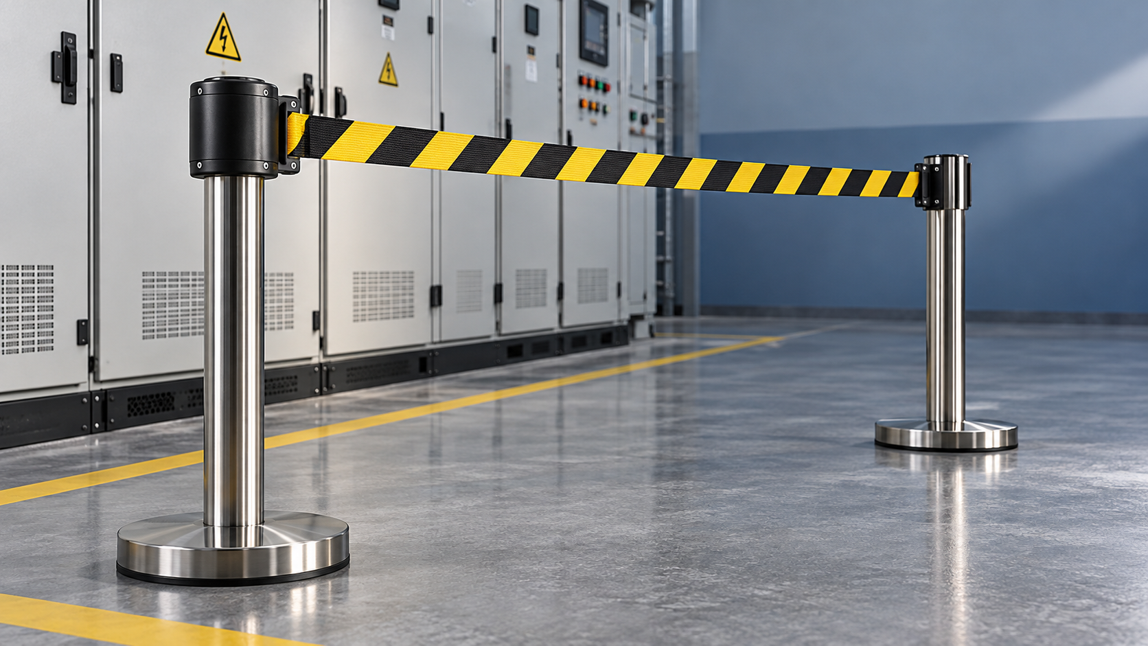
Retractable safety barrier systems are suitable for marking controlled access near live electrical equipment when their location, stability, and operating method support the electrical safety plan. A retractable belt provides a visible boundary; it does not establish an electrically safe working condition, prevent electric shock, or protect against an arc flash. Its use must preserve the approach distances and access restrictions determined for the equipment and task.
The first decision is whether a visual access barrier is sufficient for the foreseeable exposure. A belt across an aisle can discourage entry into a maintenance area. It cannot reliably stop someone reaching over it, passing underneath, or carrying a conductive ladder beyond it. Where those actions could expose a person to live parts, stronger access controls or a different work arrangement are necessary.
Place the boundary from the hazard, not from the convenient mounting point
A wall bracket beside a switchboard or a magnetic receiver on an enclosure often looks like a convenient starting point. That position is acceptable only after the electrical boundaries, working space, door movement, and access routes have been assessed. Mounting convenience does not determine a safe distance.
Shock exposure and arc-flash exposure require separate consideration. Shock approach boundaries relate to proximity to exposed energized parts. An arc-flash boundary relates to potential thermal exposure from an arc event. Their locations need not coincide, and a belt positioned to control one exposure does not automatically address the other. No universal belt offset is suitable for every voltage, equipment condition, and maintenance activity.
Measure the proposed barrier location against the actual energized parts and task configuration. The front of a closed enclosure can be a misleading reference when maintenance involves opening doors, removing covers, or withdrawing equipment. The assessment must also consider movement of tools, test leads, long materials, and body parts beyond the standing position.
Where a belt marks a required limit, allow for foreseeable displacement. A sagging span, a leaning post, or a person pressing against the webbing can move the apparent boundary toward the equipment. Establish the installation position so these movements do not defeat the intended separation. A layout that works only while every component remains perfectly aligned is unsuitable for an active work area.
Read material claims at the assembly level
“Plastic,” “nonmetallic,” and “insulated” describe different things. A polymer post or woven belt does not establish a voltage rating for the complete barrier. Moisture, contamination, pigments, fasteners, and internal mechanisms affect electrical behavior. A retractable head can contain a metallic spring even when its outer housing is plastic.
Electrical performance claims need evidence tied to the exact model and intended use. Relevant documentation identifies the tested assembly, test conditions, acceptance criteria, and limitations. A material datasheet or test result for an unrelated component cannot establish that a finished retractable barrier provides protection near exposed live conductors.
Flame behavior also requires careful interpretation. A flame-retardant belt is not an arc-rated protective barrier. Where arc exposure is relevant, ordinary webbing and housings must not be credited with reducing incident energy or shielding nearby personnel. Their placement should also avoid introducing loose material into ventilation openings or equipment mechanisms.
Installation details that change the result
Portable posts offer flexible layouts, but their stability depends on base design, floor condition, belt tension, and incidental contact. A heavy base alone does not prove that a long span will remain stable. Smooth floors, sloped surfaces, vibration, and uneven outdoor paving alter how the assembly behaves.
Assess the assembled layout at the intended extension. The receiver must hold securely, the belt must remain visible, and the posts must resist the foreseeable pulls associated with normal access control. Conduct this assessment away from exposed energized parts before deployment. Do not use a trial installation beside live conductors to discover whether a post will tip.
Wall-mounted units remove floor bases from walkways but introduce mounting constraints. Fixings need a suitable supporting surface, and installation must not compromise an electrical enclosure. Drilling into switchgear or attaching hardware to equipment requires explicit engineering acceptance. Magnetic attachments require a suitable surface and adequate retention; they must not be treated as approved simply because they stick.
The belt’s movement matters as much as its static position. During connection or retrieval, an uncontrolled end fitting can swing or recoil. Position the reel and receiver so installation and removal can occur from the permitted side without reaching into a restricted area. Select a retraction mechanism appropriate to the task and follow its operating instructions.
Maintain access to emergency exits, isolation points, operating handles, and emergency equipment. A belt crossing an escape route creates a different problem even when it marks the electrical work area clearly. Where an access opening is necessary, define its location and control method instead of relying on repeated unhooking at whichever point is convenient.
Match the barrier to the actual access problem
In an indoor electrical room with closed equipment, a retractable barrier can distinguish a temporary maintenance zone from the normal pedestrian route. The boundary must accommodate the anticipated door and equipment positions. If opening a compartment changes the exposure, reassess the layout before that change occurs.
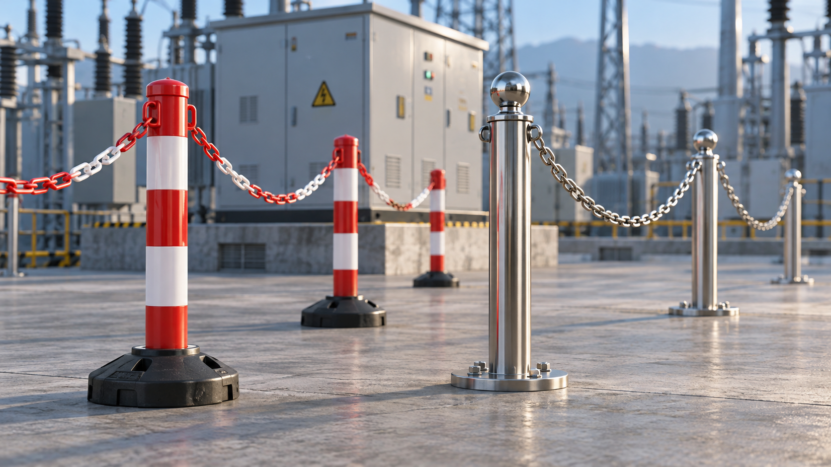
At an outdoor substation, wind can make the webbing flutter, obscure its message, or pull on the posts. Rain and surface contamination can also change electrical behavior and mechanical retention. Long spans across uneven ground deserve particular attention because sag and base movement combine. Where the layout cannot remain stable and legible, a more suitable physical barrier is required.
During industrial maintenance, the controlling issue is often traffic rather than weather. Material handling, trolleys, and mobile equipment can displace lightweight posts without a deliberate attempt to enter. A retractable belt provides no vehicle-impact protection. Traffic segregation must be established separately where a collision could push people or equipment toward the electrical hazard.
A belt is also inadequate where unattended access by unauthorized people is foreseeable and entry would create serious exposure. Locked access, rigid guarding, or a controlled enclosure may be necessary. If the task requires proximity that the proposed arrangement cannot safely support, de-energization and the applicable isolation process take priority over changing the barrier style.
Make the boundary understandable during the task
Color alone rarely communicates the full restriction. The boundary needs a clear meaning: whether entry is prohibited, controlled through a designated point, or limited to a defined activity. Wording should remain readable from the expected approach directions, including where the belt twists or its reverse side faces the walkway.
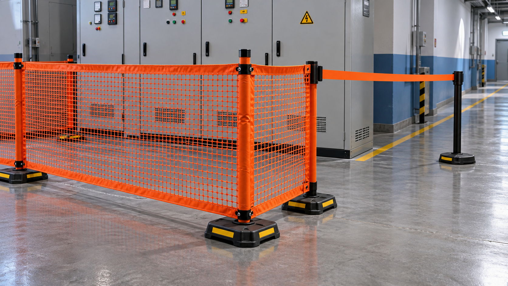
A single belt also leaves a large physical opening above and below it. Additional belt levels can improve visual definition, but they do not convert the system into a guardrail, fall-protection system, or electrically protective screen. Where the required function is to prevent bodily access or stop objects reaching live parts, use a system designed and verified for that function.
Temporary access arrangements need ownership throughout the work. Record who controls entry, when the boundary must change, and what happens if a post moves or a receiver releases. A displaced barrier requires work to pause wherever its loss removes a necessary protection. Simply reconnecting it without reviewing the cause leaves the same failure available to recur.
Keep storage and preparation outside the controlled area
Repeated trips for missing equipment create unnecessary boundary crossings. Preparing the required insulated tools, test equipment, grounding accessories, and PPE before establishing the work area reduces that disruption. Storage should allow inspection status and equipment identity to be confirmed without placing cabinets or open doors in the working clearance.
A Heavy-Duty Electrical Safety Equipment Cabinet for Insulated Tools & PPE can serve as the organized storage point outside the controlled area, with shelves, drawers, hooks, and tool panels selected around the actual equipment list. Cabinet dimensions, shelf loads, and the weight distribution of heavier items need confirmation before the layout is approved. Lockable storage supports controlled access to equipment; optional ventilation, heating, or dehumidification must be specified against the storage requirements of the contents.
The storage location does not extend the protection provided by the barrier. A cabinet placed too close to the work zone can obstruct movement, encourage reaching across the belt, or become an unintended mounting surface. Establish its position as part of the room layout, including door swing and retrieval space.
Acceptance evidence and conditions for removal from service
For acceptance, match the delivered barrier to the approved configuration: reel, belt, receiver, posts, bases, and mounting accessories. Substituting a lighter base or different receiver can change performance even when the visible belt appears identical. Keep model identification and supporting documentation linked to the assembly so replacements do not gradually create an unverified combination.
Before each deployment, inspect for conditions that affect the intended function. Frayed edges, unreadable warnings, cracked housings, loose mountings, unreliable latches, and irregular retraction each justify corrective action. A belt that retracts successfully can still have a damaged receiver; mechanical operation alone is insufficient evidence of serviceability.
Cleaning methods must suit the webbing, housing, and mechanism. Solvents, abrasive treatment, or unapproved lubricants can damage materials or interfere with retention. Equipment exposed to significant contamination, impact, or suspected electrical contact needs assessment under the applicable maintenance process before reuse. Appearance alone cannot confirm continued suitability.
At a shift change or task transition, confirm that the boundary still matches the equipment state. An arrangement established for inspection with covers closed may no longer be adequate after access panels are removed. Remove the temporary barrier only after the work area has been formally released and the access restriction is no longer required.
Recommend
 Nov 01, 2026
Plastic vs. Steel Barrier Stands: Which Suits Substation Maintenance?
Are plastic barrier stands better than steel ones for substation maintenance? Compare electrical considerations, stability, and durability to choose the right system for your crew.
- Nov 01, 2026
Is Mesh More Visible Than a Single Belt Around a Work Area?
Is a mesh barrier easier to see than a single belt around a work area? Compare visibility, lighting, and site conditions to choose the right boundary for electrical maintenance.
- Oct 31, 2026
How Do You Evaluate Slow-Retracting Safety Barriers?
Evaluate slow retracting safety barriers with practical checks for controlled return, secure mounting, and durability. Discover how to choose the right barrier for electrical work zones.