English
 Español
 Português
 Français
 Deutsch
 русский
 한국어
 にほんご
 हिन्दी, हिंदी
 বাংলা
 Bahasa Indonesia
 Türkçe
 Việt
 dansk
 čeština
 עִבְרִית Ivrit
 Filipino/Pilipino
 български език (Bǎlgarski jazik)
 suomi
 norsk
 język polski
 ไทย
 ກະຣຸນາ
 Bahasa Melayu
 ភាសាខ្មែរ
 ဗာရမ်
 اردو
 فارسی
 Italiano
 Nederlands
 svenska
 Монгол хэл
 नेपाली
 සිංහල
 Ўзбек тили
 پښتوتۆرکجه
 Ελληνικά
 српски / srpski
 magyar
 українська
 Kiswahili
 Қазақ тілі
 Română
 Hrvatski
 Bosanski
 Kreyòl ayisyen
 አማርኛ
 Hausa
 Yorùbá
 Igbo
Wall-Mounted or Freestanding Retractable Tape Barrier for Narrow Aisles?
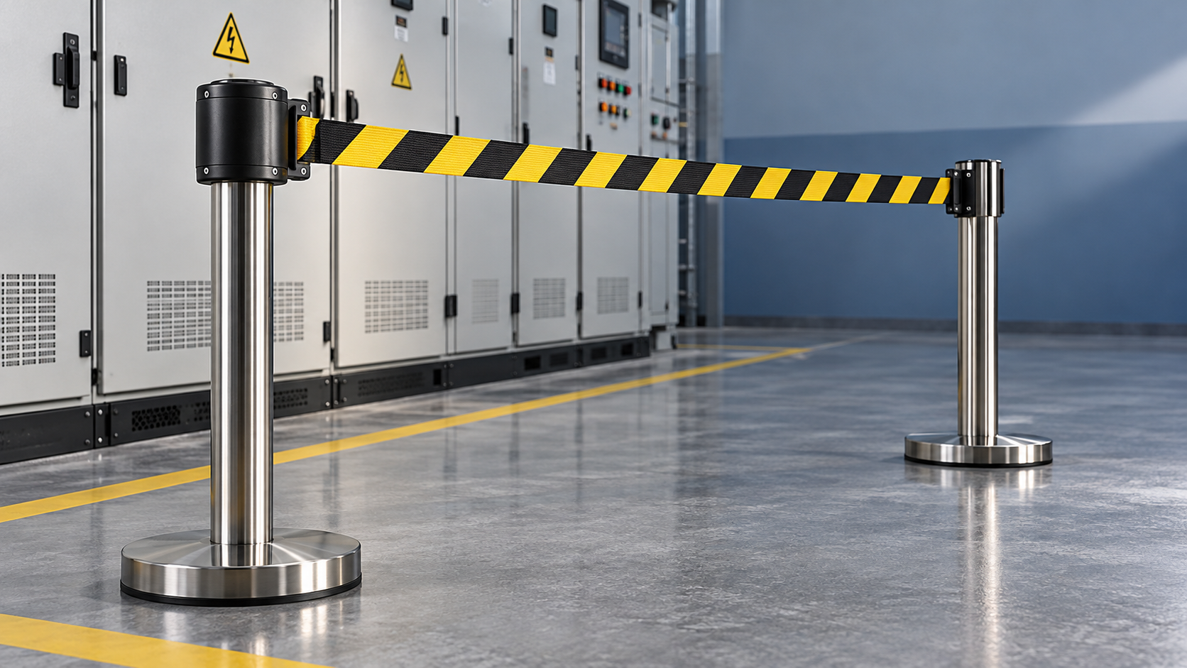
Choose a wall-mounted retractable tape barrier when the same narrow aisle is closed repeatedly, suitable mounting surfaces are available, and floor obstructions would compromise passage. Choose a freestanding arrangement when the restricted area moves with maintenance work and there is enough room for the complete base footprint. Where neither arrangement preserves required access, relocate the closure point rather than forcing a barrier into the narrowest section.
The decision starts with the aisle in its working condition: cabinet doors open, temporary leads routed, equipment being moved, and emergency equipment accessible. A barrier that fits an empty corridor can become an obstruction during servicing. In electrical rooms, the belt marks an access boundary; it provides no electrical insulation and does not establish safe working distances from energized equipment.
Compare the space each arrangement actually occupies
Wall-mounted units remove posts and bases from the floor, but their housings and receivers still project into the aisle. Freestanding posts provide placement flexibility, although the base usually determines whether they fit. Comparing only the housing width or post diameter gives an incomplete picture.
A fixed wall-to-wall closure is a strong candidate for wall mounting. A temporary boundary around changing repair work favors freestanding posts. Mixed arrangements, such as a wall cassette connected to a portable receiver post, require assessment of both the mounting connection and the post’s stability under belt tension.
Measure clearance with the equipment in use
Record the narrowest usable width along the approach, through the barrier location, and beyond it. Include handles, pipework, cable trays, columns, and other projections at the heights where people or transported equipment pass. Floor width alone does not describe the available route.
For freestanding models, measure to the outer edge of each base. A post positioned beside a cabinet can appear clear while its base extends into the walking line. Moving the post closer to the cabinet might then prevent a door from opening fully or obstruct access to a lower panel.
For wall-mounted models, assess the cassette and receiver with the belt both extended and retracted. A projecting receiver remains a snag point after the aisle reopens. Mounting behind a door can conceal the unit or allow impact when the door swings; mounting on the opposite wall can place it directly in the path of a maintenance trolley.
The available width must be assessed against the site’s applicable access, working-space, and escape requirements. A retractable belt does not make an obstructed route acceptable merely because it can be disconnected. If the aisle forms part of a required exit route, the closure arrangement needs explicit review within the site’s access-control and emergency arrangements.
Wall mounting succeeds or fails at the attachment points
A wall-mounted cassette creates a load path through the bracket, fixings, and substrate. Belt tension pulls on the assembly during normal use; abrupt extension, accidental contact, or uncontrolled retraction adds transient loading. Fixings therefore need to suit the actual wall construction, rather than just the holes supplied in the bracket.
Solid masonry, hollow partitions, cladding, and structural steel require different attachment decisions. Surface condition also matters: cracked material, loose coatings, and corrosion can undermine an otherwise suitable installation. Obtain the manufacturer’s mounting instructions and confirm that the proposed substrate can support the specified attachment.
Electrical cabinets should not be treated as convenient mounting surfaces without engineering approval. Drilling can affect enclosure integrity, create swarf near electrical components, or conflict with internal equipment. Even an external bracket can obstruct ventilation, labels, door seals, or maintenance access.
Magnetic mounting avoids drilling only where the support is suitable. Holding performance depends on steel thickness, surface geometry, coatings, cleanliness, and the direction of loading. A magnet’s stated pull-off force does not directly establish resistance to sideways sliding under an extended belt. Require suitability for the intended arrangement.
The receiver deserves the same attention as the cassette. Poor alignment encourages twisting, edge wear, and awkward connection. Position both components so the belt runs freely without rubbing against corners or passing across moving doors.
Rated belt length is only one part of usable reach
Measure the actual line between the cassette outlet and the receiver. The room’s nominal width excludes bracket offsets, recesses, and any diagonal routing. For portable posts, establish their final positions before measuring: moving bases out of a walkway often increases the required span.
Select a belt with sufficient reach for the measured layout while remaining within the manufacturer’s operating limits. Maximum extension is a capacity figure, not evidence that the belt will remain level, retract smoothly, or suit every span up to that length. Ask for the permitted configuration and relevant performance information at the intended extension.
A longer span changes how the assembly behaves. Belt weight contributes to sag, while retraction tension acts on the mounting points or posts. Increasing spring tension to improve appearance can increase the load on a freestanding post. Assess sag, connection security, and stability together rather than treating a taut-looking belt as proof of suitability.
Avoid routing the webbing around an unapproved corner to reach an offset receiver. Friction can damage the belt edge and interfere with controlled retraction. If the required boundary turns a corner, use components intended for that geometry or revise the closure location.
Freestanding stability depends on geometry as well as weight
A heavier base is not automatically suitable for a narrow aisle. Resistance to overturning also depends on base width, post height, belt attachment height, and the direction of pull. A compact heavy base and a wider lighter base cannot be compared reliably by mass alone.
Floor interaction creates a separate failure mode. A post might resist tipping yet slide on a smooth or contaminated surface. Uneven flooring, drainage falls, damaged tiles, or cable protectors can reduce support and allow rocking. Evaluate the complete assembly on the intended floor, including any protective pads beneath the base.
Where posts carry belts in several directions, assess the permitted loading arrangement. Opposing pulls may appear balanced during setup, but disconnecting one belt changes the forces immediately. Stability should remain acceptable throughout connection, use, and removal, rather than only with every belt attached.
Repeated movement also affects practicality. A base that is awkward to relocate may be left in a passage after work ends. Storage location and handling method belong in the selection decision, especially where the aisle must return promptly to normal service.
Preserve emergency access and access to rescue equipment
The belt connection needs to be reachable from the intended approach. Release should not require leaning across the restricted area or stepping around a base into an equipment working zone. Confirm how the connector behaves under tension and whether any locking feature creates an access problem.
A breakaway connector and a manually released connector serve different purposes. Breakaway behavior can limit the consequences of accidental contact, but it also allows the boundary to open under sufficient force. A locking connection offers more deliberate control but requires a release arrangement compatible with the site’s emergency procedures. Neither feature establishes suitability for an escape route by itself.
Wall-mounted emergency equipment introduces another placement constraint. Where an Electrical Insulating Rescue Hook for Emergency Electrical Safety is stored at a designated station, the cassette, extended belt, and portable bases should leave its retrieval path clear. The FRP pole and hook head also require enough space for removal from their holder. Positioning a visual barrier must preserve access to equipment used by trained personnel under the approved emergency-response procedure.
A tape barrier is appropriate for communicating a controlled boundary where that level of separation is sufficient. Where the task requires impact resistance, fall protection, or physical prevention of entry, a different protective system is necessary.
Specify durability around the actual exposure
Indoor electrical rooms, sheltered plant areas, and exposed outdoor aisles impose different demands. For outdoor placement, confirm the complete unit’s suitability for moisture, sunlight, temperature, and wind. Wind acting on extended webbing adds movement and loading that an indoor stability assessment does not address.
Webbing condition affects both visibility and operation. Frayed edges, damaged printing, contamination, and twisting deserve attention because they can impair recognition of the boundary or interfere with winding. Select belt markings that communicate the intended restriction clearly within the site’s signage system; color alone leaves room for misunderstanding.
Retraction behavior matters in a confined passage. A controlled return reduces whipping and impact at the cassette. During evaluation, observe the return over the intended extension and the handling method specified by the manufacturer. Assess whether the belt tracks evenly and whether the connector can be guided back without awkward reaching.
Resolve the choice with a representative installation trial
A useful trial reproduces the proposed location, span, attachment method, and floor condition. Open nearby cabinet doors, move the equipment normally transported through the aisle, and demonstrate closure and reopening. Include access to emergency stations and the route used after the belt is disconnected.
For a wall-mounted candidate, record the housing projection, receiver location, substrate, fixing arrangement, and any interference with equipment. For a freestanding candidate, record the base footprint, stability at the intended belt extension, and the space needed to remove and store the posts. Photographing or marking the accepted positions helps prevent later deployment from drifting into the passage.
The final specification should state the intended span and layout, mounting or base requirements, environmental exposure, connector behavior, and retraction characteristics. Accept the arrangement only when it performs in that defined configuration. If adequate clearance requires moving a base into a cabinet access zone or attaching a cassette to an unsuitable surface, change the boundary location before selecting the hardware.
Recommend
 Nov 01, 2026
Plastic vs. Steel Barrier Stands: Which Suits Substation Maintenance?
Are plastic barrier stands better than steel ones for substation maintenance? Compare electrical considerations, stability, and durability to choose the right system for your crew.
- Nov 01, 2026
Is Mesh More Visible Than a Single Belt Around a Work Area?
Is a mesh barrier easier to see than a single belt around a work area? Compare visibility, lighting, and site conditions to choose the right boundary for electrical maintenance.
- Oct 31, 2026
How Do You Evaluate Slow-Retracting Safety Barriers?
Evaluate slow retracting safety barriers with practical checks for controlled return, secure mounting, and durability. Discover how to choose the right barrier for electrical work zones.