
 English
 Español
 Português
 Français
 Deutsch
 русский
 한국어
한국어 にほんご
にほんご हिन्दी, हिंदी
 বাংলা
বাংলা Bahasa Indonesia
 Türkçe
 Việt
Việt dansk
dansk čeština
 עִבְרִית Ivrit
 Filipino/Pilipino
 български език (Bǎlgarski jazik)
 suomi
suomi norsk
norsk język polski
 ไทย
ไทย ກະຣຸນາ
 Bahasa Melayu
 ភាសាខ្មែរ
 ဗာရမ်
ဗာရမ် اردو
اردو فارسی
فارسی Italiano
 Nederlands
 svenska
 Монгол хэл
 नेपाली
 සිංහල
සිංහල Ўзбек тили
 پښتوتۆرکجه
 Ελληνικά
 српски / srpski
 magyar
 українська
 Kiswahili
 Қазақ тілі
 Română
 Hrvatski
 Bosanski
 Kreyòl ayisyen
 አማርኛ
አማርኛ Hausa
Hausa Yorùbá
 Igbo
Igbo‹
›
Resistive Discharge Rod for High-Voltage Equipment
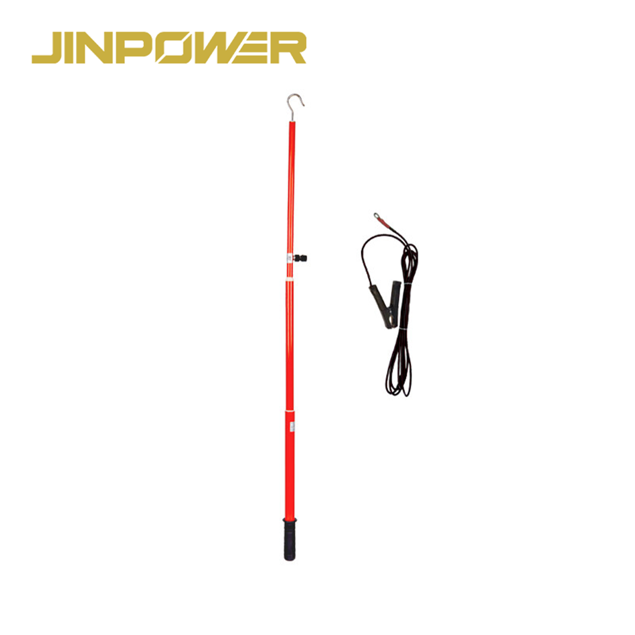
JINPOWER supplies Resistive Discharge Rods designed to release residual electrical charge from specified high-voltage equipment after shutdown and isolation. A built-in resistance element limits the initial discharge current, allowing stored electrical energy to be released according to the selected product's electrical characteristics.
This product is intended for applications where resistive discharge is required as part of an approved electrical maintenance or testing procedure. Typical application areas include capacitor banks, high-voltage cables, GIS, switchgear, substations and high-voltage test equipment, subject to the equipment requirements and product rating.
For utility companies, EPC contractors, electrical equipment distributors and maintenance teams, selecting the correct discharge rod involves more than checking the equipment voltage. Resistance value, stored energy, resistor energy capability, insulating rod dimensions and grounding connections must also be considere
All Products
Stay Connected
If you have any questions, please contact us and we will contact you as soon as possible.
Prduct Introdution
Product Highlights
- Resistive discharge function for specified electrical applications
- Built-in resistance element designed to limit initial discharge current
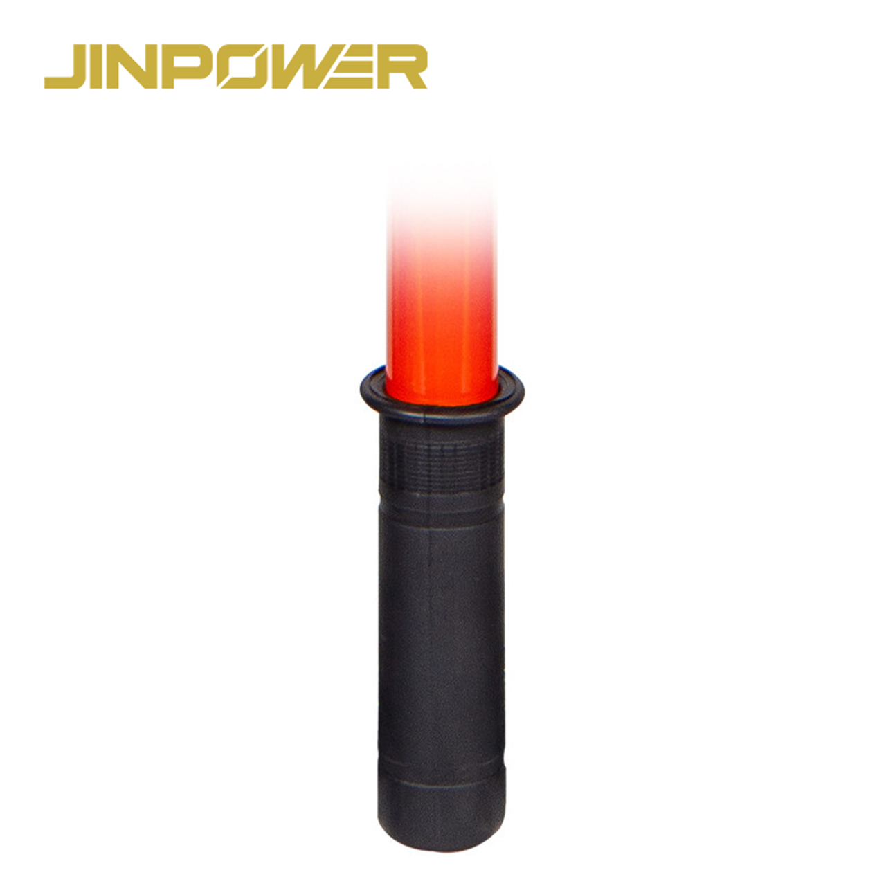
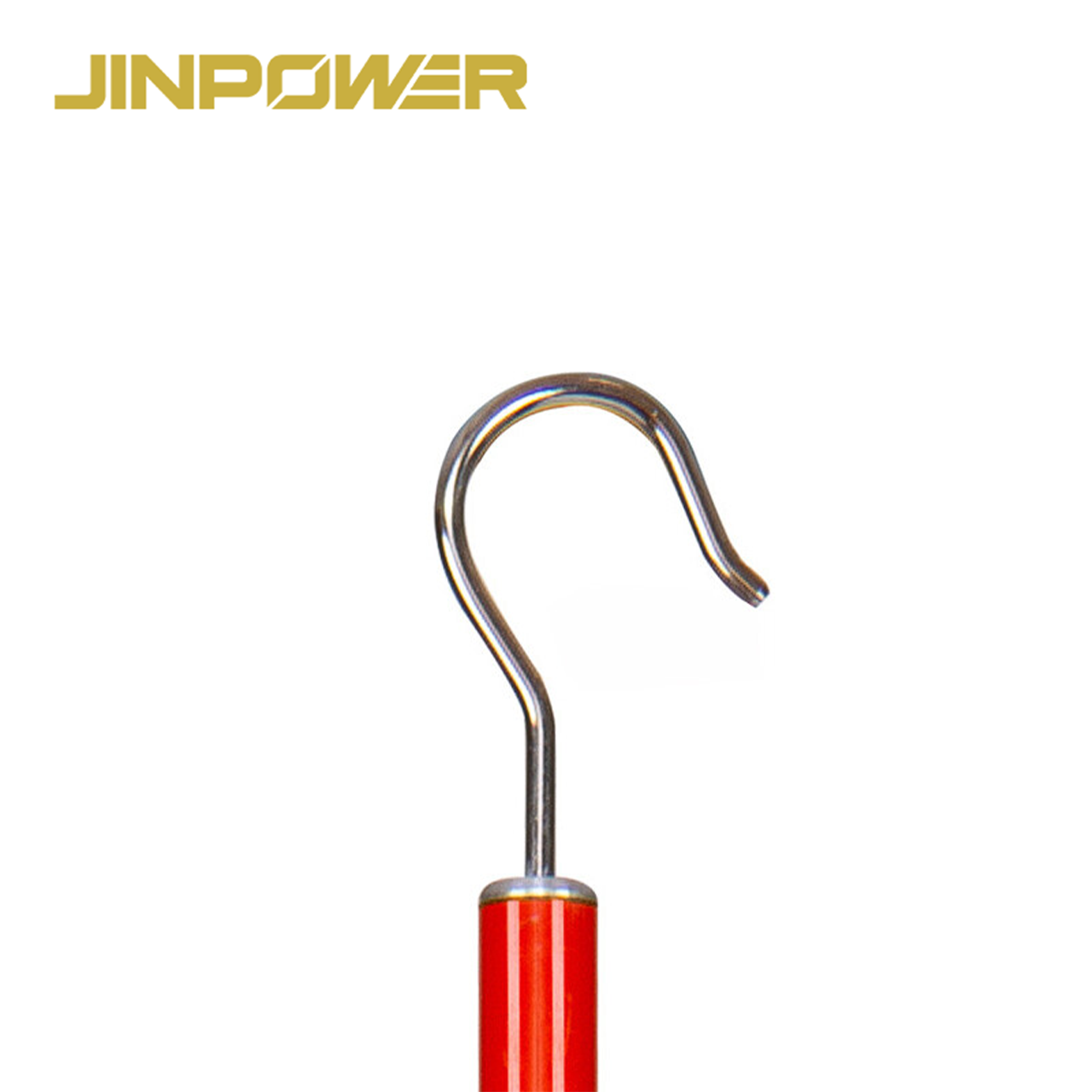
- Insulating operating rod with an electrical contact head
- Grounding lead and clamp according to the selected configuration
- Suitable for selected capacitor bank, high-voltage cable, GIS, switchgear and testing applications
- Resistance value and electrical ratings confirmed according to the applicable model specification
- Rod length, grounding lead length and connection configuration can be reviewed for project requirements
- Technical specifications and applicable inspection documents can be confirmed before bulk purchasing
Quick Technical Specifications
The following table covers the main parameters for technical review and procurement. Exact electrical ratings and dimensions should be confirmed against the selected model's approved datasheet and drawing.
For an accurate quotation, please provide the equipment type, rated voltage, required resistance value if specified, rod length, grounding lead length, quantity and applicable project requirements. Where available, include the equipment capacitance or stored-energy information so the required discharge duty can be reviewed.
How Does Resistive Discharge Work?
Electrical equipment containing capacitive elements may retain stored energy after its power supply has been disconnected. This can occur in capacitor banks, high-voltage cables and certain electrical testing arrangements.
A Resistive Discharge Rod uses a resistance element in the intended discharge path. The resistance limits the current according to the electrical conditions, allowing residual charge to decrease in a controlled manner when the tool is correctly selected and used.
1. Contact with the Designated Equipment Point
The contact head provides the intended electrical interface with the equipment being discharged. Its design must match the designated contact point and the approved application.
The rod must be used only under the applicable electrical safety procedure. Product compatibility, equipment isolation and the required voltage verification must be established before the discharge operation.
2. Current Limitation Through the Resistance Element
When the intended discharge path is established, the resistance element limits the initial discharge current. This helps avoid the sudden current associated with an uncontrolled low-resistance connection when the equipment still contains substantial stored energy.
The actual current depends on the initial voltage, resistance and circuit conditions. The resistor must also be capable of handling the energy associated with the intended application.
3. Release of Stored Electrical Energy
As the equipment discharges, its stored energy decreases. The rate of discharge depends on the equipment characteristics, resistance value and discharge configuration.
A specific discharge time should not be assumed from the product name or rated voltage alone. The required discharge conditions must be determined from the equipment manufacturer's instructions, engineering requirements and approved site procedure.
4. Verification and Subsequent Safety Measures
The completion of a resistive discharge operation does not, by itself, prove that equipment is safe to touch or work on. Any required verification, additional discharge measures or temporary protective grounding must follow the applicable procedure.
A Resistive Discharge Rod is intended for its specified discharge function. It should not automatically be treated as a replacement for a complete portable earthing and short-circuiting system.
Main Components of a Resistive Discharge Rod
The product configuration includes the components required for the intended resistive discharge function. Buyers should confirm the actual component design and dimensions against the selected model's technical drawing.
Insulating Rod
The insulating rod provides the operating section used to position the contact head while maintaining the required separation between the operator and the electrical contact point.
Rod length and effective insulating length should be selected according to the equipment, working arrangement and applicable electrical safety requirements. The total rod length alone does not establish the product's insulation rating.
Contact Head
The contact head provides the electrical interface with the designated equipment point. Its shape and dimensions should match the intended connection arrangement.
For project-specific equipment, buyers should provide connection drawings or interface dimensions when available. This helps confirm compatibility before production or order approval.
Resistance Element
The resistance element is the key component that distinguishes a Resistive Discharge Rod from a simple direct discharge tool. It limits discharge current according to its electrical characteristics and the conditions of the equipment.
Resistance value, tolerance and energy capability should be evaluated together. A resistor with the correct resistance value may still be unsuitable if its energy rating or discharge duty does not match the application.
Grounding Lead
The grounding lead provides the conductive connection toward the designated grounding point as part of the configured discharge arrangement.
Lead length, conductor specification and connection details should match the selected product and its intended application. Custom cable length should be confirmed together with the applicable electrical requirements.
Grounding Clamp
The grounding clamp connects the lead to the specified grounding point. Its dimensions and connection method must be compatible with the intended interface.
If your project uses a particular grounding terminal or connection arrangement, provide the relevant dimensions or drawing during the inquiry stage.
Typical Applications of Resistive Discharge Rods
Capacitor Banks
Capacitor banks can retain stored electrical energy after disconnection. A suitable resistive discharge arrangement may be required before maintenance or other approved work can proceed.
Selection should consider the initial voltage, capacitance, stored energy, required discharge conditions and resistor energy capability. A general-purpose description is not sufficient to establish suitability for a particular capacitor bank.
High-Voltage Cables
High-voltage cables can retain capacitive charge after isolation. The appropriate discharge method depends on the cable system, electrical characteristics, connection points and approved maintenance procedure.
Before selecting a discharge rod, confirm the cable voltage, relevant stored-energy conditions and the required discharge arrangement with the responsible engineering team.
GIS and Switchgear
Certain Gas-Insulated Switchgear (GIS) and conventional switchgear applications may require residual-charge management during maintenance or testing.
The product should only be used where the equipment manufacturer permits the application and provides an appropriate connection point. Its suitability must be confirmed against the equipment configuration and approved procedure.
High-Voltage Test Equipment
Some high-voltage testing equipment and connected test objects may retain electrical energy after testing. A suitable resistive discharge tool may form part of the approved energy-release process.
The required resistance, energy capability and connection arrangement must be appropriate for the test object and the electrical conditions involved.
Substation Maintenance
Substation maintenance procedures may involve equipment that retains residual electrical energy after isolation. A resistive discharge rod may be suitable for specified applications where the product rating and connection design meet the requirements.
The exact equipment type and discharge requirement should be identified before procurement rather than assuming that one model is suitable for every substation application.
Resistive Discharge Rod vs Resistive & Direct Discharge Rod
JINPOWER lists both Resistive Discharge Rods and Resistive & Direct Discharge Rods. Although the products are related, they serve different functional requirements and should be specified separately.
Neither product is automatically suitable for every high-voltage application. The correct choice depends on the equipment, stored-energy conditions, required discharge method and approved operating procedure.
If your project specifically requires both resistive and direct discharge functions, see our Resistive & Direct Discharge Rod.
How to Choose the Right Resistive Discharge Rod
1. Confirm the Equipment Voltage
Start by identifying the rated voltage of the equipment and the actual application conditions. Where relevant, specify whether the application involves AC, DC or a particular high-voltage testing arrangement.
The selected product must have a suitable electrical rating and insulating configuration. Do not determine suitability from rod length or appearance alone.
2. Identify the Equipment Type
Specify whether the rod will be used for a capacitor bank, high-voltage cable, GIS, switchgear, test equipment or another application.
Different equipment can retain different amounts of energy even when their nominal voltage ratings are similar. The equipment type helps establish which technical information is needed for selection.
3. Confirm the Resistance Requirement
If your project specifies a resistance value or tolerance, include it in the RFQ. If the value has not been determined, provide the equipment characteristics and applicable engineering requirements for technical review.
Resistance value should not be selected in isolation. It must be assessed together with the initial voltage, discharge current, stored energy and resistor energy capability.
4. Review Stored Energy and Discharge Duty
For equipment containing capacitive elements, stored energy is an important factor in determining the required discharge capability.
Where available, provide capacitance, initial voltage, stored-energy data and the required discharge conditions. These details help determine whether the selected resistance element is appropriate for the application.
5. Confirm Rod and Insulating Section Length
Specify the required total rod length and effective insulating length. The dimensions must suit the equipment access point and applicable operating requirements.
If the project specifies particular dimensions, provide the relevant drawing or technical specification for review.
6. Match the Grounding Lead and Clamp
Confirm the required grounding lead length, conductor specification and clamp connection. The complete connection arrangement must match the intended equipment and grounding point.
For non-standard interfaces, include connection dimensions or drawings in the inquiry to reduce compatibility issues before ordering.
7. Confirm Testing and Documentation Requirements
Before bulk purchasing, identify the required technical datasheet, drawing, resistance verification, applicable insulation test documentation and other project-specific inspection records.
Confirm which documents are available for the actual selected model rather than assuming that every product configuration has the same test coverage.
Testing and Quality Verification
For electrical maintenance tools, quality verification should cover the product configuration and the technical requirements relevant to its intended application. Appearance alone does not establish electrical suitability.
Depending on the selected model and agreed inspection plan, the following items may be relevant to product acceptance.
Electrical Specification Checks
- Resistance value and tolerance against the approved specification
- Applicable voltage and electrical application requirements
- Resistor energy capability and specified discharge duty
- Consistency between the approved design and supplied configuration
- Applicable electrical performance records, where required
Mechanical and Dimensional Checks
- Total rod length and effective insulating section
- Contact head dimensions and connection arrangement
- Grounding lead length and specified conductor details
- Grounding clamp type and connection compatibility
- Surface condition and visible mechanical damage
- Product identification and required markings
Insulation and Electrical Test Documentation
Where required by the product specification or project, confirm the applicable insulation tests, resistance measurements and other electrical performance verification. The test method and acceptance criteria should correspond to the actual product and its intended use.
A basic resistance measurement or visual inspection alone does not establish the complete electrical suitability of a high-voltage discharge tool.
Technical Documents
Depending on the order, relevant documents may include a technical datasheet, approved drawing, resistance verification, applicable insulation test records and other agreed inspection documents.
If a utility or EPC project requires a specific standard or third-party verification, state the requirement before order confirmation so its applicability and documentation can be reviewed.
Safety Requirements for Resistive Discharge Applications
A Resistive Discharge Rod is intended for use by trained and authorized electrical personnel. Product selection and operation must follow the equipment manufacturer's instructions, the applicable electrical safety requirements and the approved site procedure.
Isolation and Voltage Verification
Disconnection alone does not prove that equipment is safe. Required isolation and voltage verification must be completed using the approved procedure and suitable equipment before the relevant work proceeds.
Where voltage detection is required, see our High Voltage Detector range for related electrical safety equipment.
Stored Energy and Discharge Conditions
Equipment may retain electrical energy after isolation. The required discharge method must account for the actual equipment characteristics and the approved procedure.
Do not assume that a fixed waiting time or the presence of a resistance element guarantees that all stored energy has been released. Any required verification and subsequent safety measures must follow the applicable instructions.
Discharge and Protective Earthing Are Different Functions
A resistive discharge tool releases residual electrical energy through its specified resistance path. Temporary protective earthing and short-circuiting equipment serves a separate function and must be selected according to its own electrical ratings and intended application.
A Resistive Discharge Rod should not automatically be treated as a replacement for a rated portable earthing and short-circuiting set.
Related Grounding and Electrical Safety Products
Depending on your project requirements, you may also need related grounding equipment or a discharge rod with a different functional configuration.
- Resistive & Direct Discharge Rod — for projects requiring both resistive and direct discharge functions in the selected configuration.
- Grounding Cable — for projects requiring a specified grounding cable or cable component.
- Portable Earthing and Short-Circuiting Set — for specified temporary protective earthing and short-circuiting applications.
- High Voltage Detector — for voltage verification as part of an approved electrical safety procedure.
What Should You Include in Your RFQ?
Providing complete technical information at the inquiry stage helps reduce specification gaps, quotation revisions and product compatibility issues.
If your project has an existing discharge tool specification or connection drawing, include it with the inquiry. This helps the technical team review the required configuration more accurately.
Frequently Asked Questions
What is a Resistive Discharge Rod?
A Resistive Discharge Rod is an electrical discharge tool that uses a resistance element to limit current while releasing residual electrical charge from specified equipment. Its suitability depends on the equipment characteristics, product rating and approved operating procedure.
Why does a discharge rod use a resistance element?
The resistance element limits the initial discharge current according to the electrical conditions. This helps reduce the risk associated with uncontrolled direct discharge when equipment still contains stored energy.
What equipment can a Resistive Discharge Rod be used for?
Typical application areas include capacitor banks, high-voltage cables, GIS, switchgear, substations and high-voltage test equipment. The selected model must be confirmed as suitable for the specific equipment and discharge requirement.
How do I select the correct resistance value?
Resistance selection depends on the equipment voltage, stored energy, required discharge conditions and resistor energy capability. Follow the approved equipment specification or engineering requirements rather than selecting a resistance value from voltage alone.
Does the rod have a universal voltage rating?
No. The applicable voltage and insulating configuration depend on the selected model and its technical documentation. Confirm the rating before using the product for a particular application.
What is the difference between a Resistive Discharge Rod and a Resistive & Direct Discharge Rod?
A Resistive Discharge Rod provides the specified resistive discharge function. A Resistive & Direct Discharge Rod combines resistive discharge with an additional direct discharge function. Choose according to the required application and approved equipment procedure.
Can a Resistive Discharge Rod replace a Portable Earthing Set?
Not automatically. A discharge rod is intended for its specified discharge function, while a Portable Earthing Set is designed for defined temporary protective earthing and short-circuiting duties. The required equipment must be determined by the approved safety procedure.
Can the rod length and grounding lead length be customized?
Rod and grounding lead requirements can be reviewed according to the available product configuration. Any change affecting insulation, resistance or electrical performance requires technical confirmation.
What documents should I request before bulk purchasing?
Depending on the project, request the technical datasheet, approved drawing, resistance verification, applicable insulation test records and other agreed inspection documents. Confirm which documents are available for the exact product model.
What information is needed for a quotation?
Provide the equipment type, rated voltage, required resistance value if specified, rod length, grounding lead length, quantity and project requirements. Stored-energy information and connection drawings are also helpful when available.
Request Resistive Discharge Rod Details and Pricing
If you are sourcing Resistive Discharge Rods for capacitor banks, high-voltage cable systems, switchgear, substations or electrical testing applications, send JINPOWER your technical requirements for review.
Please include the equipment voltage, equipment type, required resistance value if specified, rod length, grounding lead length, quantity and applicable project requirements. Where available, provide the equipment capacitance, stored-energy information and connection drawing.
JINPOWER can review the requested configuration against the available product documentation and clarify the information required before quotation and order confirmation.
Inquiry